Description
🔧 Arduino Pro Mini – ATmega328P Compact Microcontroller Board
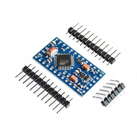
The Arduino Pro Mini is an ultra-compact microcontroller development board based on the ATmega328P chip, designed for permanent installations and space-constrained projects. Measuring just 33mm × 18mm, this tiny powerhouse features 14 digital I/O pins (6 with PWM), 8 analog inputs, 16MHz clock speed, and 32KB flash memory. Perfect for wearable electronics, drones, robotics, embedded systems, and projects where size matters. Unlike the Arduino Uno, the Pro Mini requires an external FTDI or USB-to-Serial adapter for programming, making it ideal for production and permanent deployments.
✨ Key Highlights
- 📐 Ultra-Compact Size – Only 33mm × 18mm – smallest Arduino board
- 💻 ATmega328P Microcontroller – Same chip as Arduino Uno
- ⚡ 16 MHz Clock Speed – Fast processing for real-time applications
- 🔌 14 Digital I/O Pins – 6 with PWM capability
- 📊 8 Analog Inputs – 10-bit ADC resolution (more than Uno!)
- 💾 32 KB Flash Memory – Ample program storage
- 🔋 Low Power Options – 3.3V or 5V versions available
- 💰 Cost-Effective – Affordable for production deployments
- 📍 Breadboard Friendly – Perfect 0.1″ pin spacing
- 🔓 Arduino Compatible – Use familiar Arduino IDE and libraries
📊 Technical Specifications
| Specification |
Details |
| 💻 Microcontroller |
ATmega328P (8-bit AVR) |
| ⚡ Operating Voltage |
3.3V or 5V (model dependent) |
| 🔋 Input Voltage |
3.35-12V (3.3V model), 5-12V (5V model) |
| ⏱️ Clock Speed |
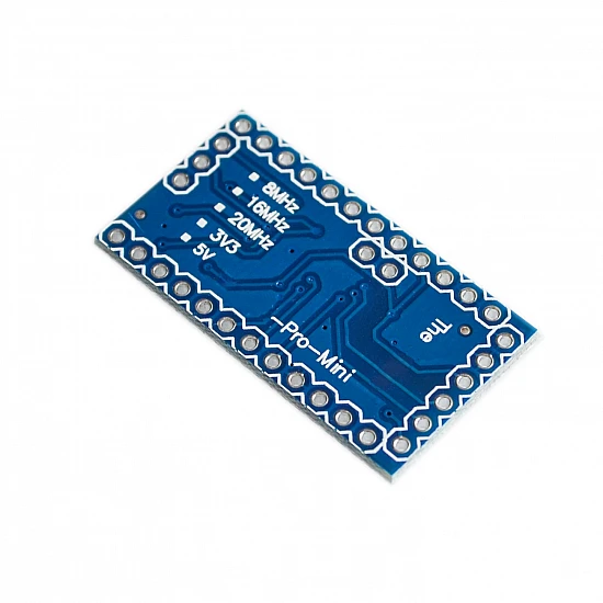
8 MHz (3.3V) or 16 MHz (5V) |
| 💾 Flash Memory |
32 KB (0.5 KB bootloader) |
| 🧠 SRAM |
2 KB |
| 💿 EEPROM |
1 KB |
| 📌 Digital I/O Pins |
14 (6 PWM) |
| 📊 Analog Input Pins |
8 (A0-A7, 10-bit ADC) |
| 💡 DC Current per I/O |
40 mA max |
| 🔌 Programming Interface |
6-pin header (FTDI compatible) |
| 📡 Communication |
UART, I2C, SPI |
| 📏 Dimensions |
33mm × 18mm (1.3″ × 0.7″) |
| ⚖️ Weight |
2 grams (approximately) |
| 🔌 Pin Pitch |
2.54mm (0.1″ standard breadboard) |
🔋 3.3V vs 5V Model Comparison
| Feature |
3.3V Model (8MHz) |
5V Model (16MHz) |
| Operating Voltage |
3.3V |
5V |
| Clock Speed |
8 MHz |
16 MHz |
| Input Voltage Range |
3.35V – 12V |
5V – 12V |
| Power Consumption |
Lower (~10mA) |
Higher (~20mA) |
| Best For |
Battery projects, 3.3V sensors |
Standard projects, 5V sensors |
| Sensor Compatibility |
3.3V sensors (ESP, SD cards) |
5V sensors (most Arduino) |
📌 Pin Configuration
| Pin Type |
Pins Available |
Special Functions |
| Digital I/O |
D0-D13 (14 total) |
Standard input/output |
| PWM Pins |
D3, D5, D6, D9, D10, D11 |
8-bit PWM output (0-255) |
| Analog Input |
A0-A7 (8 total) |
10-bit ADC (0-1023) |
| Serial (UART) |
RX (D0), TX (D1) |
Hardware serial communication |
| I2C/TWI |
SDA (A4), SCL (A5) |
Multi-device communication |
| SPI |
MOSI (D11), MISO (D12), SCK (D13), SS (D10) |
High-speed communication |
| Interrupts |
D2 (INT0), D3 (INT1) |
External interrupts |
| Power Pins |
VCC, GND, RAW |
Power input/output |
🎯 Perfect For
| Application |
Description |
| 👕 Wearable Electronics |
Fitness trackers, smart clothing, LED accessories |
| 🚁 Drones & RC Projects |
Flight controllers, telemetry, camera gimbals |
| 🤖 Robotics |
Small robots, sensor nodes, motor control |
| 📦 Embedded Systems |
Permanent installations, production deployments |
| 🔋 Battery-Powered Projects |
Portable sensors, remote monitoring, data loggers |
| 🏠 Home Automation |
Smart sensors, compact controllers, IoT nodes |
| 🎨 Art Installations |
Interactive displays, LED art, kinetic sculptures |
| 📡 Wireless Sensors |
Environmental monitoring, mesh networks |
🔧 Programming Setup
| Step |
Action |
| 1. Get FTDI Adapter |
Purchase FTDI or USB-to-Serial adapter (match voltage!) |
| 2. Connect Adapter |
Connect 6-pin header: GND→GND, VCC→VCC, TXO→RXI, RXI→TXO, DTR→GRN |
| 3. Install Drivers |
Install FTDI or CH340 drivers for your adapter |
| 4. Arduino IDE Setup |
Tools → Board → Arduino Pro or Pro Mini |
| 5. Select Voltage & Speed |
Tools → Processor → Choose 3.3V 8MHz or 5V 16MHz |
| 6. Select COM Port |
Tools → Port → Select your FTDI adapter port |
| 7. Upload Code |
Write code and click Upload button |
| 8. Disconnect Adapter |
Remove FTDI adapter after programming (optional) |
🔌 FTDI Connection Pinout
| FTDI Pin |
Pro Mini Pin |
Function |
| GND |
GND (BLK) |
Ground connection |
| CTS |
Not connected |
Leave empty |
| VCC |
VCC |
Power (3.3V or 5V – match board!) |
| TXO |
RXI |
FTDI transmit → Pro Mini receive |
| RXI |
TXO |
FTDI receive → Pro Mini transmit |
| DTR |
GRN |
Auto-reset for programming |
📦 Package Contents
- ✅ 1x Arduino Pro Mini Development Board (3.3V or 5V)
- ✅ 1x Pin header strip (requires soldering)
- ⚠️ Note: FTDI/USB-to-Serial adapter NOT included (required for programming)
- ⚠️ Note: USB cable NOT included
- ⚠️ Note: Headers require soldering to board
- ⚠️ Note: Breadboard, jumper wires sold separately
✅ Key Advantages
| Feature |
Benefit |
| 📐 Ultra-Compact |
Smallest Arduino form factor – fits anywhere |
| 💰 Cost-Effective |
Affordable for production and multi-unit projects |
| 🔋 Low Power |
3.3V version ideal for battery-powered applications |
| 📊 More Analog Pins |
8 analog inputs vs 6 on Arduino Uno |
| 📍 Breadboard Friendly |
Perfect spacing for easy prototyping |
| 🔌 Detachable Programmer |
Remove FTDI after upload – cleaner deployment |
| ⚙️ Arduino Compatible |
Use all Arduino libraries and code examples |
| 🏭 Production Ready |
Ideal for permanent installations and mass production |
⚠️ Important Notes
- 🔌 FTDI adapter required – Cannot program via USB without external adapter
- ⚡ Voltage matching – Use 3.3V FTDI with 3.3V board, 5V FTDI with 5V board
- 🔧 Soldering required – Headers must be soldered to board before use
- 📌 Correct processor – Select proper voltage/speed in Arduino IDE (3.3V/8MHz or 5V/16MHz)
- 💡 Current limits – Max 40mA per pin (higher than Uno’s 20mA)
- 🔋 Power input – Can use RAW pin (up to 12V) or VCC pin (regulated voltage only)
- ⚠️ No onboard LED – Pin 13 LED not included (add external LED for testing)
- 🔌 DTR connection – Required for auto-reset during programming
🔋 Power Supply Options
| Power Method |
Voltage |
Best For |
| RAW Pin |
5-12V |
Battery packs, wall adapters (uses onboard regulator) |
| VCC Pin |
3.3V or 5V |
Pre-regulated power (bypasses regulator) |
| FTDI Adapter |
3.3V or 5V |
Programming and testing only |
| LiPo Battery (3.3V) |
3.7V |
Portable projects with 3.3V board |
| AA Batteries (5V) |
6V (4×1.5V) |
Portable projects with 5V board via RAW |
| USB Power Bank |
5V |
5V board via VCC pin (requires step-down for 3.3V) |
🔍 Troubleshooting
| Problem |
Solution |
| Upload Failed |
Check FTDI connections, verify voltage/speed selection in IDE |
| Board Not Detected |
Install FTDI/CH340 drivers, check USB cable |
| Wrong Bootloader |
Select correct processor (3.3V/8MHz or 5V/16MHz) |
| Code Runs Slow |
Verify 16MHz selected for 5V board (not 8MHz) |
| No Auto-Reset |
Connect DTR pin from FTDI to GRN on Pro Mini |
| Power Issues |
Check voltage matches board (3.3V or 5V) |
💡 Pro Tips
- 🔧 Solder headers carefully – Use flux and solder each pin cleanly for good contact
- 📍 Mark your board – Label voltage (3.3V or 5V) to avoid confusion later
- 🔋 Low power mode – Use sleep modes for battery projects to extend runtime
- 💾 Test before deploying – Fully test with FTDI connected before permanent installation
- ⚡ Power from RAW – Use RAW pin with battery packs for regulated power
- 🔌 Keep FTDI handy – You’ll need it for every code update
- 📦 Buy multiple boards – Very affordable – stock up for projects
- 🛡️ Add protection – Consider adding reverse polarity protection diode
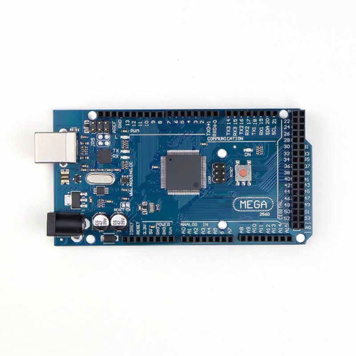
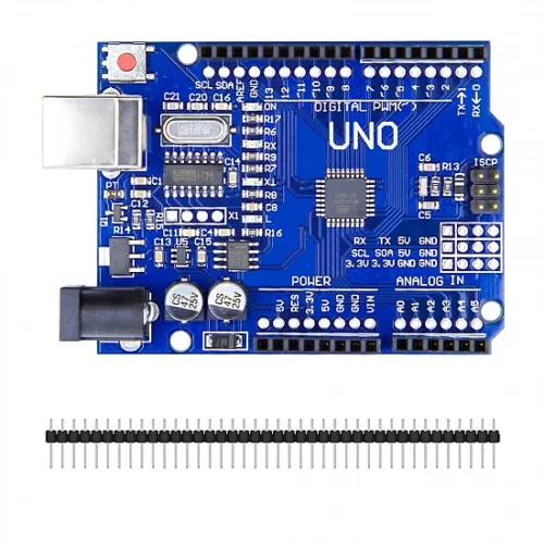
🆚 Pro Mini vs Arduino Uno
| Feature |
Arduino Pro Mini |
Arduino Uno R3 |
| Size |
33mm × 18mm |
68.6mm × 53.4mm |
| Weight |
2g |
25g |
| USB Programming |
❌ Needs FTDI adapter |
✅ Built-in USB |
| Analog Inputs |
8 pins (A0-A7) |
6 pins (A0-A5) |
| Voltage Options |
3.3V or 5V |
5V only |
| Cost |
💰 Very low |
💰💰 Higher |
| Best For |
Production, embedded, wearables |
Learning, prototyping, shields |
🛡️ Product Information
✅ Arduino Pro Mini – ATmega328P Compact Development Board
✅ Ultra-compact size: 33mm × 18mm – smallest Arduino form factor
✅ 14 digital I/O pins (6 PWM) + 8 analog inputs (more than Uno!)
✅ 16 MHz (5V) or 8 MHz (3.3V) clock speed
✅ 32 KB flash, 2 KB SRAM, 1 KB EEPROM
✅ UART, I2C, SPI communication protocols
✅ Breadboard friendly with 0.1″ pin spacing
✅ Arduino IDE compatible – use all libraries and examples
✅ Low power consumption – ideal for battery projects
✅ Perfect for production, embedded systems, wearables
✅ Available in 3.3V (8MHz) or 5V (16MHz) versions
✅ Cost-effective for multi-unit deployments
⚠️ Important: FTDI or USB-to-Serial adapter required for programming (NOT included). Headers require soldering before use. Select correct processor in Arduino IDE: 3.3V/8MHz or 5V/16MHz. Use matching voltage FTDI adapter (3.3V with 3.3V board, 5V with 5V board). Max 40mA per I/O pin. RAW pin accepts 5-12V, VCC pin needs regulated voltage only. No onboard USB – cannot program without external adapter. DTR connection required for auto-reset during upload. Specify voltage when ordering (3.3V or 5V model).