Description
📱 T-Relay 12V/24V – Smart WiFi Relay Module with ESP32
The T-Relay 12V/24V is an advanced IoT relay control board featuring an integrated ESP32 microcontroller, dual-voltage support (12V/24V), and built-in WiFi/Bluetooth connectivity. This all-in-one smart relay module combines industrial-grade relays with modern wireless control capabilities, making it perfect for home automation, industrial IoT, remote switching, and smart building applications. With onboard voltage regulation, OLED display support, and programmable ESP32, this module eliminates the need for separate microcontrollers and driver circuits.
✨ Key Highlights
- 📱 ESP32 Built-in – Dual-core WiFi + Bluetooth microcontroller integrated
- ⚡ Dual Voltage Support – Works with 12V or 24V input (auto-switching)
- 🔌 Multiple Relay Options – 1, 2, 4, or 6 channel versions available
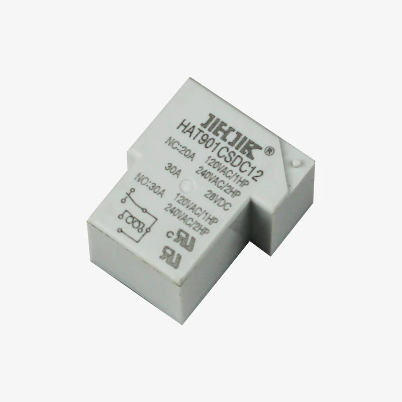
- 💡 10A Relay Contacts – Switch high-power loads up to 250VAC/30VDC
- 📟 OLED Display Support – SH1106/SSD1306 display connector included
- 🌐 WiFi + Bluetooth – Wireless control via smartphone or cloud
- 🔧 Onboard Driver Circuit – No external components needed
- 🔋 USB-C Programming – Easy firmware updates and debugging
- 📡 GPIO Expansion – Additional pins for sensors and peripherals
- 🏠 Smart Home Ready – Compatible with Home Assistant, MQTT, Blynk
📊 Technical Specifications
| Specification |
Details |
| 🖥️ Microcontroller |
ESP32-WROOM-32 (Dual-core Xtensa LX6) |
| ⚙️ CPU Clock Speed |
160MHz / 240MHz |
| 💾 Flash Memory |
4MB |
| 🧠 SRAM |
520KB |
| 📶 WiFi |
802.11 b/g/n (2.4GHz) |
| 📡 Bluetooth |
Bluetooth 4.2 (Classic + BLE) |
| ⚡ Input Voltage |
12V or 24V DC (±10%) |
| 🔋 Voltage Range |
10.8V – 26.4V DC (Operating range) |
| 💡 Power Consumption |
~1W (idle), ~2-3W (all relays active) |
| 🔌 Number of Relays |
1 / 2 / 4 / 6 channels (variant dependent) |
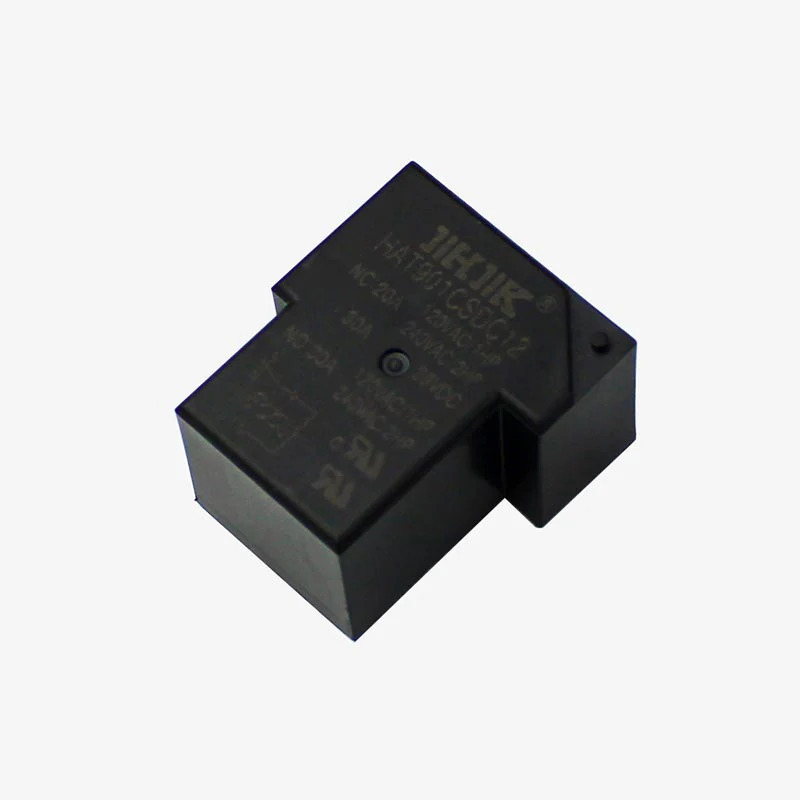
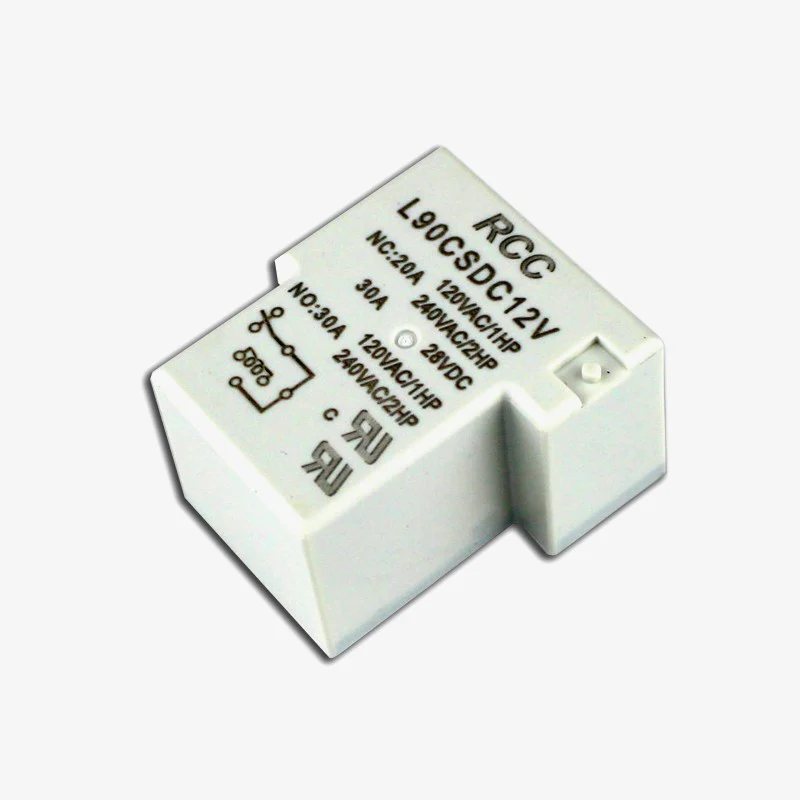
| ⚡ Relay Type |
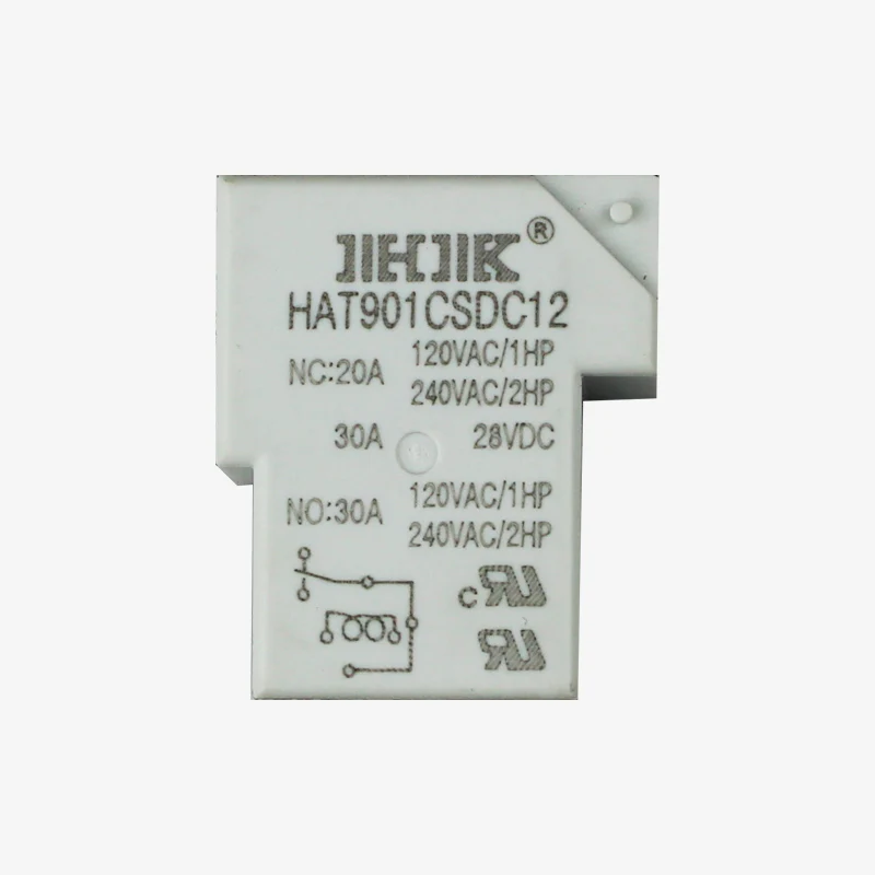
SPDT (Form C) – NO, NC, COM contacts |
| 💪 Contact Rating |
10A @ 250VAC / 10A @ 30VDC (per relay) |
| 🔒 Contact Material |
Silver alloy (AgNi) |
| 🔌 USB Interface |
USB-C (CH340C USB-to-Serial) |
| 📟 Display Connector |
4-pin I2C (for SH1106/SSD1306 OLED) |
| 🔢 GPIO Expansion |
Multiple ESP32 GPIOs available on headers |
| 🔘 Buttons |
BOOT button, RESET button |
| 💡 LED Indicators |
Power LED, relay status LEDs |
| 📏 Dimensions |
Varies by channel count (~80mm x 55mm typical) |
| 🌡️ Operating Temperature |
-10°C to +60°C |
| ⚖️ Weight |
~30-50g (depends on channel count) |
🔌 Available Channel Configurations
| Model |
Relay Channels |
Best For |
| T-Relay 1CH |
1 Relay |
Single appliance control, simple switching |
| T-Relay 2CH |
2 Relays |
Dual device control, motor direction |
| T-Relay 4CH |
4 Relays |
Multi-room lighting, HVAC control |
| T-Relay 6CH |
6 Relays |
Comprehensive automation, building control |
📟 OLED Display Connector
| Pin |
Function |
Connection |
| 1 |
GND |
Ground |
| 2 |
VCC |
3.3V Power |
| 3 |
SCL |
I2C Clock (GPIO22) |
| 4 |
SDA |
I2C Data (GPIO21) |
🔌 Terminal Block Connections
| Terminal |
Function |
Notes |
| VIN (+) |
12V or 24V DC input |
Connect to positive of power supply |
| GND (-) |
Ground/Common |
Connect to negative of power supply |
| Relay 1-6 COM |
Common contact |
Moving contact of relay |
| Relay 1-6 NO |
Normally Open |
Closed when relay energized |
| Relay 1-6 NC |
Normally Closed |
Open when relay energized |
🎯 Perfect For
| Application |
Description |
| 🏠 Smart Home Automation |
WiFi-controlled lights, fans, appliances, curtains |
| 📱 Remote Control Systems |
Control devices from anywhere via smartphone app |
| 🌐 IoT Cloud Integration |
AWS IoT, Google Cloud, Azure, Home Assistant |
| 🏭 Industrial Monitoring |
Remote equipment control with status feedback |
| 🌡️ Climate Control |
Smart thermostats, HVAC automation, temperature control |
| 🌱 Greenhouse Automation |
Irrigation, ventilation, lighting schedules |
| 🔐 Access Control |
Smart locks, gate operators with WiFi control |
| 💡 Smart Lighting |
Multi-zone lighting with scheduling and scenes |
| 📊 Energy Management |
Load scheduling, peak shaving, power monitoring |
| 🚨 Alarm Systems |
Siren control, emergency shutoff, notifications |
| 🤖 Robotics & Automation |
Multi-motor control, sequential operations |
| 🎭 Stage/Event Control |
Lighting control, prop automation, effects |
📦 Package Contents
- ✅ 1x T-Relay Board (12V/24V compatible)
- ✅ Pre-installed ESP32 module
- ✅ Terminal blocks for power and relay connections
- ✅ GPIO header pins (may require soldering)
- ✅ OLED display connector (display sold separately)
- ⚠️ Note: 12V/24V power supply NOT included
- ⚠️ Note: USB-C cable may or may not be included
- ⚠️ Note: OLED display sold separately
💻 Programming & Software Support
| Platform |
Support Level |
| 🔷 Arduino IDE |
✅ Full Support (Most Popular) |
| ⚙️ ESP-IDF |
✅ Official Espressif SDK |
| 🌐 PlatformIO |
✅ Recommended for advanced users |
| 🐍 MicroPython |
✅ Supported |
| 📱 ESPHome |
✅ Excellent (Home Assistant integration) |
| 🔧 Tasmota |
✅ Compatible firmware |
| ☁️ Blynk |
✅ Mobile app control ready |
| 📡 MQTT |
✅ Full protocol support |
🏠 Smart Home Integration
| Platform |
Integration Method |
Features |
| Home Assistant |
ESPHome / MQTT |
✅ Full automation, scenes, voice control |
| Google Home |
Via Home Assistant / Cloud |
✅ Voice commands, routines |
| Amazon Alexa |
Via MQTT bridge / Cloud |
✅ Voice control, skills |
| Apple HomeKit |
Via Homebridge / HAP-NodeJS |
✅ Siri control, automation |
| Node-RED |
MQTT / HTTP |
✅ Visual flow programming |
| OpenHAB |
MQTT binding |
✅ Open-source automation |
| Blynk IoT |
Blynk library |
✅ Custom mobile app interface |
⚡ Power Supply Requirements
| Configuration |
Minimum Supply |
Recommended |
| 1 Channel (12V) |
12V 0.5A |
12V 1A (for loads) |
| 2 Channel (12V) |
12V 0.5A |
12V 1.5A |
| 4 Channel (12V) |
12V 0.5A |
12V 2A |
| 6 Channel (12V) |
12V 1A |
12V 2A |
| 1 Channel (24V) |
24V 0.3A |
24V 0.5A |
| 2-6 Channel (24V) |
24V 0.5A |
24V 1A |
🔧 GPIO Pin Assignment (Typical)
| GPIO |
Function |
Notes |
| GPIO21 |
I2C SDA (OLED) |
Display data line |
| GPIO22 |
I2C SCL (OLED) |
Display clock line |
| GPIO16-19 |
Relay Control (varies) |
Drives relay transistors |
| GPIO0 |
BOOT button |
Flash mode / user button |
| GPIO32-35 |
Available for expansion |
User GPIO (ADC capable) |
| RX, TX |
Serial debug |
UART0 for USB communication |
⚠️ Important Notes & Warnings
- ⚡ 12V OR 24V input – Board auto-detects, do NOT exceed 26.4V
- 🔌 Separate power for board and loads – Board uses <1W, plan load power separately
- ⚠️ AC VOLTAGE IS DANGEROUS – Hire qualified electrician for mains wiring
- 🔒 Each relay isolated – Can switch different voltages simultaneously
- 💪 10A per relay maximum – Total board current limited by terminals and traces
- 🔥 Inductive loads require derating – Motors/solenoids 50% reduction
- 📡 WiFi antenna placement – Keep away from metal enclosures for best range
- 🌡️ Temperature monitoring – Board may get warm with all relays active
- 🔧 Firmware required – Board ships with basic firmware, custom programming recommended
- 🛡️ Enclosure recommended – Protect exposed terminals and electronics
- ⚡ Flyback protection built-in – On-board diodes protect relay coils
- 📱 OTA updates supported – Update firmware wirelessly after initial setup
🛠️ Getting Started (Quick Setup)
- 🔌 Connect Power – Wire 12V or 24V DC to VIN (+) and GND (-) terminals
- 💡 Verify Power LED – Board power indicator should light up
- 📥 Install Arduino IDE – Download from arduino.cc
- ⚙️ Add ESP32 Board Support – Use board manager URL from Espressif
- 🔌 Connect USB-C Cable – Plug into computer for programming
- 🎯 Select Board – Choose “ESP32 Dev Module” in Arduino IDE
- 📍 Select Port – Choose correct COM/ttyUSB port
- 📝 Upload Test Code – Start with relay blink example
- 📡 Configure WiFi – Add your network credentials to code
- 🌐 Test Web Interface – Access board’s IP address in browser
- 🏠 Integrate with Smart Home – Set up ESPHome or MQTT
- 🚀 Connect Loads – Wire devices to relay terminals (power OFF first!)
💡 Example Arduino Code (Basic Relay Control)
| Code Snippet |
#include <WiFi.h>
// Define relay pins (adjust based on your T-Relay model)

const int RELAY1 = 16;

const int RELAY2 = 17;

const int RELAY3 = 18;

const int RELAY4 = 19;
// WiFi credentials

const char* ssid = "YourWiFiSSID";

const char* password = "YourPassword";
WiFiServer server(80);
void setup() {

Serial.begin(115200);
// Initialize relay pins

pinMode(RELAY1, OUTPUT);

pinMode(RELAY2, OUTPUT);

pinMode(RELAY3, OUTPUT);

pinMode(RELAY4, OUTPUT);
// All relays OFF initially

digitalWrite(RELAY1, LOW);

digitalWrite(RELAY2, LOW);

digitalWrite(RELAY3, LOW);

digitalWrite(RELAY4, LOW);
// Connect to WiFi

WiFi.begin(ssid, password);

while (WiFi.status() != WL_CONNECTED) {

delay(500);

Serial.print(".");

}

Serial.println("WiFi connected!");

Serial.print("IP: ");

Serial.println(WiFi.localIP());
server.begin();

}
void loop() {

// Handle web requests for relay control

// Full web server code here...

}
// Add web server code to control relays via HTTP
|
✅ Advantages of T-Relay vs Separate Components
| Feature |
T-Relay Advantage |
| 🔧 All-in-One Design |
ESP32 + relays + drivers integrated – no wiring between boards |
| ⚡ Dual Voltage Input |
12V/24V auto-detection – universal power compatibility |
| 💡 Built-in Drivers |
No external transistors/MOSFETs needed |
| 📟 OLED Support |
Ready-to-use display connector for status display |
| 🔌 Professional Terminals |
Screw terminals for secure, maintenance-friendly connections |
| 💻 USB Programming |
No FTDI adapter needed – USB-C direct connection |
| 🏠 Smart Home Ready |
Pre-designed for ESPHome and MQTT integration |
| 📱 OTA Updates |
Update firmware wirelessly without physical access |
| 🛡️ Protection Circuits |
Built-in flyback diodes and voltage regulation |
| 📐 Compact PCB |
Professional layout vs breadboard mess |
🔍 Troubleshooting Guide
| Problem |
Possible Cause |
Solution |
| Board Won’t Power On |
No power or voltage too low |
✅ Check 12V/24V supply, verify polarity, measure voltage |
| USB Not Detected |
Driver not installed or bad cable |
✅ Install CH340 driver, try different USB cable |
| Relay Doesn’t Switch |
Wrong GPIO pin in code |
✅ Verify relay pin assignments for your model |
| WiFi Won’t Connect |
Wrong credentials or 5GHz network |
✅ ESP32 only supports 2.4GHz – check SSID/password |
| Load Doesn’t Turn On |
Wiring error or blown fuse |
✅ Check COM-NO connection, test relay with multimeter |
| Board Resets Randomly |
Power supply insufficient |
✅ Use higher current PSU, check voltage under load |
| OLED Not Working |
Wrong I2C address or library |
✅ Scan I2C bus, verify 0x3C address, check SH1106 vs SSD1306 |
| Upload Failed |
Not in boot mode |
✅ Hold BOOT button while clicking upload |
💡 Pro Tip