

Description
🔌 8-Channel 5V/12V Relay Module – Professional Multi-Relay Board with Optocoupler Isolation
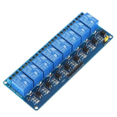
The 8-Channel 5V/12V Relay Module is a professional-grade relay control board featuring eight independent relay channels with built-in driver circuits, optocoupler isolation, LED indicators, and screw terminals. This comprehensive module allows simultaneous control of up to eight separate loads, making it perfect for complex automation, smart home systems, industrial control, and multi-zone applications. With dual voltage support (5V or 12V) and complete electrical isolation per channel, this module provides safe, reliable switching for demanding projects requiring multiple outputs.
✨ Key Highlights
- ⚡ 8 Independent Relay Channels – Control up to 8 separate loads simultaneously
- 🔋 Dual Voltage Support – Works with 5V or 12V input (jumper selectable)
- 🔒 Full Optocoupler Isolation – PC817 isolation on every channel
- 🔌 10A Per Channel – Each relay rated 250VAC/30VDC @ 10A
- 💡 9x LED Indicators – Power LED + status LED for each of 8 relays
- 🔧 Professional Screw Terminals – Easy, secure wire connections for all contacts
- 📱 3.3V Logic Compatible – Works with ESP8266, ESP32, Raspberry Pi
- 🛡️ Complete Driver Circuits – No external components needed
- 🔄 Flexible Configuration – Active High/Low selectable per channel
- 🏭 Industrial-Grade PCB – Professional board with mounting holes
📊 Technical Specifications
| Specification | Details |
|---|---|
| 🔌 Module Type | 8-Channel Relay Module Board |
| 🔢 Number of Relays | 8 independent channels |
| ⚡ Operating Voltage | 5V DC or 12V DC (jumper selectable per channel) |
| 🔋 Voltage Range | 4.5-5.5V (5V mode) / 10.8-14.4V (12V mode) |
| 💡 Control Signal Input | 3.3V – 5V compatible (optocoupler isolated) |
| 📡 Trigger Current | ~2-5mA per channel (low current, MCU-friendly) |
| 🔋 Module Current Draw | ~320mA @ 5V (all relays ON) / ~180mA @ 12V (all relays ON) |
| 🔧 Trigger Logic | Active High or Active Low (jumper selectable per channel) |
| 🔒 Isolation | PC817 optocoupler per channel (8x total) |
| 🔌 Relay Type | SRD-05VDC-SL-C or SRD-12VDC-SL-C (SPDT) x8 |
| ⚡ Contact Rating (AC) | 10A @ 250VAC / 10A @ 125VAC per channel |
| 🔋 Contact Rating (DC) | 10A @ 30VDC / 10A @ 28VDC per channel |
| 💪 Maximum Switching Power | 2500VA (AC) / 300W (DC) per channel |
| 🔌 Contact Configuration | SPDT (Form C) x8 – Each has NO, NC, COM terminals |
| 💡 LED Indicators | 1x Power LED (red), 8x Relay Status LEDs (green/blue) |
| 🔧 Terminals | Screw terminals for power and all 24 relay contacts (8×3) |
| 📌 Control Interface | 10-pin header (VCC, GND, IN1-IN8) |
| ⏱️ Response Time | ≤10ms (pickup), ≤5ms (release) per relay |
| 🔄 Relay Lifespan | 100,000 operations (rated load) per relay |
| 🌡️ Operating Temperature | -10°C to +60°C |
| 💧 Humidity | 20% to 80% RH (non-condensing) |
| 📏 PCB Dimensions | ~138mm x 52mm x 19mm (L x W x H) |
| ⚖️ Weight | ~95g |
| 🔩 Mounting Holes | 4x M3 mounting holes (3mm diameter) |
🔌 Terminal & Pin Configuration
| Terminal/Pin | Function | Connection |
|---|---|---|
| VCC (DC+) | Power Input | Connect to +5V or +12V power supply |
| GND (DC-) | Ground | Connect to power supply ground |
| IN1 to IN8 | Relay Control Inputs | Connect to MCU GPIO pins (3.3V or 5V) |
| CH1-CH8 COM | Common Contacts | Connect to load or power source (8x) |
| CH1-CH8 NO | N.O. Contacts | Closed when corresponding relay energized (8x) |
| CH1-CH8 NC | N.C. Contacts | Open when corresponding relay energized (8x) |
🔄 Channel Assignment
| Control Pin | Relay Channel | Status LED | Screw Terminals |
|---|---|---|---|
| IN1 | Relay 1 | LED1 | CH1: COM, NO, NC |
| IN2 | Relay 2 | LED2 | CH2: COM, NO, NC |
| IN3 | Relay 3 | LED3 | CH3: COM, NO, NC |
| IN4 | Relay 4 | LED4 | CH4: COM, NO, NC |
| IN5 | Relay 5 | LED5 | CH5: COM, NO, NC |
| IN6 | Relay 6 | LED6 | CH6: COM, NO, NC |
| IN7 | Relay 7 | LED7 | CH7: COM, NO, NC |
| IN8 | Relay 8 | LED8 | CH8: COM, NO, NC |
💡 LED Indicator Status
| LED | Color | Status Indication |
|---|---|---|
| Power LED | Red | ON = Module powered correctly |
| Relay 1-8 LEDs | Green/Blue | ON = Corresponding relay energized (contact switched) |
🎯 Perfect For
| Application | Description |
|---|---|
| 🏠 Whole Home Automation | 8-room lighting, multi-zone control, complete house automation |
| 🏢 Building Management | Office lighting zones, HVAC control, access control systems |
| 🌱 Advanced Garden Automation | 8-zone irrigation, multiple pumps, lighting, ventilation, heaters |
| 🏭 Industrial Control Panels | Multi-equipment control, process automation, conveyor systems |
| 🎭 Stage/Event Control | Multi-zone lighting, effects control, equipment sequencing |
| 💡 Smart Lighting Systems | 8-zone lighting, scene control, architectural lighting |
| 🏊 Pool/Spa Automation | Pump, heater, lights, jets, sanitizer, waterfall control |
| 🔐 Multi-Door Access Control | 8 doors, gates, locks, turnstiles, barriers |
| 🚨 Security Systems | Multi-zone alarms, sirens, strobes, notification systems |
| 📡 IoT Central Control Hub | WiFi-controlled multi-device automation, smart building |
| 🌡️ Complex HVAC Systems | Multi-zone heating, cooling, fans, dampers, humidifiers |
| 🤖 Advanced Robotics | Multi-motor control, actuators, pneumatics, complex automation |
📦 Package Contents
- ✅ 1x 8-Channel Relay Module Board (5V/12V compatible)
- ✅ 8x Pre-installed relays with optocouplers
- ✅ Complete screw terminals for power and all 24 relay contacts
- ✅ 10-pin control header (may require male-to-female jumper wires)
- ✅ 9x LED indicators pre-installed (power + 8x relay status)
- ⚠️ Note: Jumper wires NOT included (Dupont wires recommended)
- ⚠️ Note: 5V/12V power supply NOT included (min 2A for 5V, 1A for 12V)
- ⚠️ Note: Mounting screws NOT included
💻 Arduino Code Examples
Basic 8-Channel Sequential Control
| Code Snippet |
|---|
|
Multi-Zone Lighting Control
| Code Snippet |
|---|
|
ESP32 WiFi 8-Channel Web Control
| Code Snippet |
|---|
|
✅ Advantages of 8-Channel Module
| Feature | Benefit |
|---|---|
| 🔢 8 Independent Channels | Control 8 separate loads – complete automation solution |
| 📐 Highly Space Efficient | Much smaller than 8 individual relay modules |
| 💰 Cost Effective | Significantly cheaper than buying 8 separate modules |
| 🔌 Simplified Wiring | Single power connection for all 8 relays |
| 🔒 8x Optocoupler Isolation | Each channel independently isolated for maximum safety |
| 💡 Individual LED Status | Visual feedback for all 8 channels at a glance |
| ⚡ Full 10A Per Channel | All 8 relays can handle 10A simultaneously (total 80A capacity) |
| 🔧 Per-Channel Configuration | Mix Active High/Low as needed for each relay |
| 🏭 Professional Build Quality | Industrial-grade PCB with proper isolation and protection |
| 🌐 Complete Automation Hub | Central control point for whole-home or building automation |
⚠️ Important Safety & Usage Notes
- ⚡ Adequate power supply required – Min 2A @ 5V or 1A @ 12V for all relays
- 🔌 Common ground essential – Module GND and MCU GND must connect
- ⚠️ AC VOLTAGE IS DANGEROUS – 250VAC can be lethal; hire qualified electrician
- 🔒 Verify all jumper settings – Check Active High/Low for each channel before testing
- 💪 10A maximum per channel – Do not exceed per-relay rating
- 🔥 Heat dissipation critical – With 8 relays under load, adequate cooling essential
- 🛡️ Independent but shared power – All channels draw from same power supply
- 📏 Organize AC wiring carefully – Keep high voltage traces separated and labeled
- 🌡️ Monitor operating temperature – Module generates significant heat with multiple loads
- 🔧 Double-check all 24 terminals – Verify tight connections on all screw terminals
- ⚡ Individual circuit protection – Use separate fuse for each load circuit
- 📱 GPIO pin planning – Reserve 8 consecutive or well-organized GPIO pins
- 🔋 Inrush current consideration – Switching 8 loads simultaneously may cause voltage dip
- 🏭 Professional enclosure required – Use properly rated electrical enclosure for safety
🔍 Troubleshooting Guide
| Problem | Possible Cause | Solution |
|---|---|---|
| Only Some Relays Work | Insufficient power supply current | ✅ Use higher capacity PSU (min 2A @ 5V, 1A @ 12V) |
| Relays Won’t All Switch Together | Voltage drop when all activate | ✅ Add 1000µF capacitor across VCC/GND, use regulated PSU |
| Specific Channel Not Working | Bad optocoupler or relay on that channel | ✅ Test IN signal with multimeter, check jumper, replace module if needed |
| Power LED On, No Relays Work | Control signals not connected or wrong voltage | ✅ Verify IN1-IN8 connections, check common ground |
| Module Resets Randomly | Power supply overload or voltage sag | ✅ Use larger PSU, add bulk capacitor (2200µF), check wire gauge |
| Inconsistent Operation | Poor power supply regulation | ✅ Use quality switching PSU, avoid cheap adapters |
| Module Gets Very Hot | Multiple high-current loads or inadequate ventilation | ✅ Add cooling fan, reduce load currents, improve airflow |
| ESP32 Crashes When Switching | Shared power causing voltage fluctuation | ✅ Use separate regulated 3.3V for ESP32, common ground only |
🔌 Power Supply Sizing Guide
| Voltage | Minimum Current | Recommended Current | Notes |
|---|---|---|---|
| 5V | 1.5A | 2A or higher | ~320mA for all 8 relays + margin |
| 12V | 500mA | 1A or higher | ~180mA for all 8 relays + margin |
| Note: Add MCU current draw (ESP32 ~500mA, Arduino ~50mA) if powering from same supply | |||
💡 Pro Tips for 8-Channel Projects
- 🔧 Use terminal block labeling – Number each relay 1-8 clearly on enclosure
- 📏 Color-code all wiring – Different colors for each relay circuit
- ⚡ Staged power-up – Turn on relays sequentially to reduce inrush
- 🛡️ DIN rail mounting – Professional installation in electrical panel
- 💾 State preservation – Save relay states to EEPROM for power loss recovery
- 📋 Comprehensive wiring diagram – Document all 24 contact connections
- 🔒 Interlock logic – Prevent conflicting relay combinations in code
- ⏰ Watchdog timer – Auto-reset if system hangs
- 🌐 Status reporting – Implement MQTT state messages for all 8 channels
- 📱 Mobile dashboard – Create 8-button interface showing all states
- 🔋 Dedicated PSU per module – Don’t share PSU with other high-current devices
- 🔧 Emergency shutoff – Physical button to turn all relays OFF
- 🌡️ Temperature monitoring – Add thermistor to detect overheating
- 📊 Usage logging – Track which relays are used most for maintenance planning
🆚 Multi-Channel Relay Module Comparison
| Feature | 1-Channel | 2-Channel | 4-Channel | 8-Channel |
|---|---|---|---|---|
| Number of Loads | 1 device | 2 devices | 4 devices | 8 devices |
| GPIO Pins Used | 1 pin | 2 pins | 4 pins | 8 pins |
| Board Size | ~50x38mm | ~51x39mm | ~75x52mm | ~138x52mm |
| Power @ 5V | ~40mA | ~80mA | ~160mA | ~320mA |
| Best For | Simple switching | Dual control | Multi-room | Complete automation |
| Complexity | ⭐ Simple | ⭐⭐ Moderate | ⭐⭐⭐ Advanced | ⭐⭐⭐⭐ Professional |
| Relative Cost | 💰 Base | 💰💰 1.5x | 💰💰💰 2.5x | 💰💰💰💰 4x |
🏠 Example 8-Zone Smart Home Setup
| Channel | Zone/Device | Load Type | Typical Use |
|---|---|---|---|
| CH1 | Living Room Lights | LED (100W) | Evening automation, scenes |
| CH2 | Kitchen Lights | LED (80W) | Motion sensor control |
| CH3 | Bedroom 1 Lights | LED (60W) | Schedule, voice control |
| CH4 | Bedroom 2 Lights | LED (60W) | Schedule, voice control |
| CH5 | Bathroom Exhaust Fan | Motor (50W) | Auto-timer, humidity sensor |
| CH6 | Outdoor Lights | LED (150W) | Dusk-to-dawn, security |
| CH7 | Garage Door Opener | Motor (500W) | Remote access, status |
| CH8 | Garden Irrigation | Solenoid (15W) | Scheduled watering zones |
🛡️ Warranty & Support
✅ Complete 8-channel relay module with all driver circuits
✅ 8x optocoupler isolation for maximum safety (PC817)
✅ High-quality 10A relays per channel (SRD series)
✅ Individual LED indicators for each relay + power LED
✅ Professional screw terminals for all 26 connections
✅ Compatible with Arduino, Raspberry Pi, ESP32, ESP8266
✅ Dual voltage support (5V/12V selectable)
✅ Independent trigger mode configuration per channel
✅ Pre-tested all 8 channels before shipping
✅ Comprehensive technical documentation and example code
✅ Industrial-grade PCB with mounting holes
✅ Fast replacement for defective units
⚠️ Important: High voltage AC wiring MUST be performed by qualified electrician. Always disconnect all power before wiring. Use properly rated electrical enclosure. Ensure adequate power supply (min 2A @ 5V or 1A @ 12V). Each relay can handle 10A independently, but consider total heat dissipation with multiple high-current loads. Provide adequate ventilation and cooling.