Description
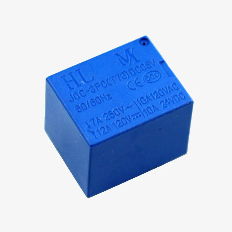
⚡ 5V SugarCube 5-Pin Relay Module – Compact Power Switching Solution
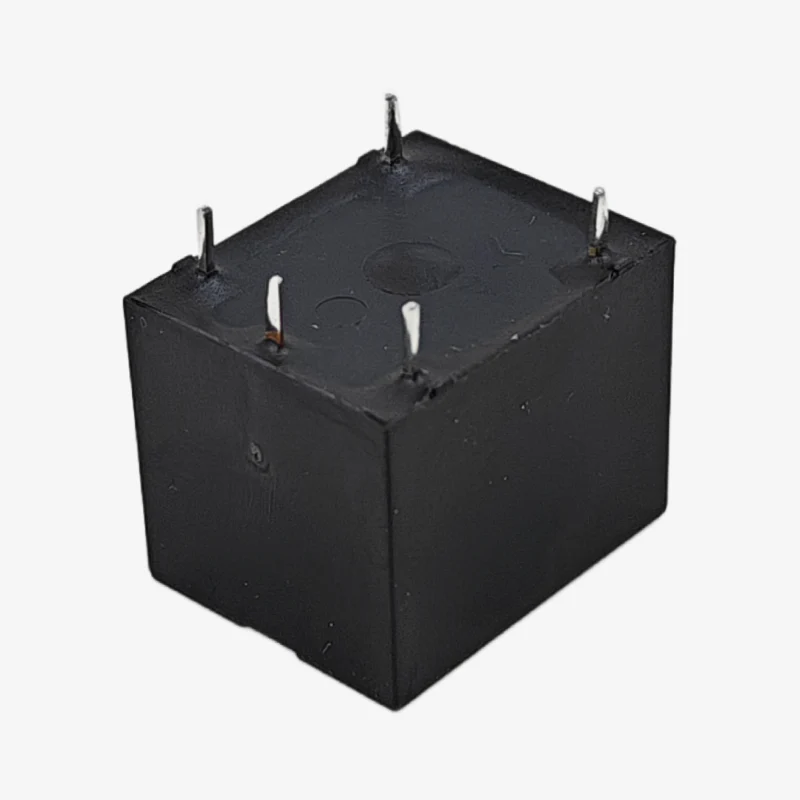
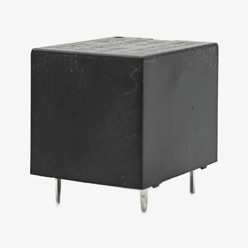
The 5V SugarCube 5-Pin Relay is a compact, reliable electromechanical relay module designed for switching high-power AC/DC loads using low-voltage microcontroller signals. With its miniature “sugar cube” form factor and 5-pin configuration, this relay is perfect for IoT automation, home automation, robotics, and industrial control applications. Capable of switching up to 10A at 250VAC or 30VDC, this relay provides safe electrical isolation between control circuits and high-power loads.
✨ Key Highlights
- ⚡ 5V Coil Voltage – Direct microcontroller compatibility (Arduino, ESP32, Raspberry Pi)
- 🔌 10A Switching Capacity – Handle appliances, motors, lights, and solenoids
- 🔒 Electrical Isolation – Safe separation between control and load circuits
- 📐 Compact SugarCube Design – Space-saving miniature form factor
- 🔄 SPDT Configuration – Single Pole Double Throw (NO + NC contacts)
- 💡 Low Power Coil – Minimal current draw (~70mA)
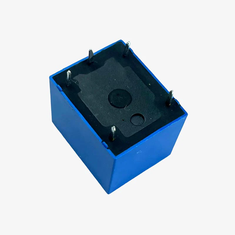
- 🔧 5-Pin Terminal – Easy PCB mounting and connections
- ⚙️ Long Lifespan – 100,000+ mechanical operations
- 🌐 Universal Compatibility – Works with all 5V logic microcontrollers
📊 Technical Specifications
| Specification |
Details |
| ⚡ Coil Voltage |
5V DC |
| 💡 Coil Current |
~70mA (typical) |
| 🔌 Contact Configuration |
SPDT (Single Pole Double Throw) |
| ⚡ Maximum Switching Voltage (AC) |
250VAC |
| 🔋 Maximum Switching Voltage (DC) |
30VDC |
| 💪 Maximum Switching Current |
10A (Resistive Load) |
| 🔌 Contact Rating |
10A @ 250VAC / 10A @ 30VDC |
| ⚙️ Contact Material |
Silver Alloy (AgNi or AgCdO) |
| 🔒 Contact Resistance |
≤100mΩ (initial) |
| ⏱️ Operating Time |
≤10ms (pickup), ≤5ms (release) |
| 🔄 Mechanical Life |
10,000,000 operations (no load) |
| ⚡ Electrical Life |
100,000 operations (rated load) |
| 🛡️ Insulation Resistance |
≥100MΩ (at 500VDC) |
| ⚡ Dielectric Strength |
1000VAC (1 minute between coil and contacts) |
| 🌡️ Operating Temperature |
-40°C to +85°C |
| 📏 Dimensions |
~19.5mm x 15.5mm x 15.5mm (LxWxH) |
| 📌 Pin Pitch |
5.0mm (standard PCB spacing) |
| ⚖️ Weight |
~8g |
🔌 5-Pin Configuration
| Pin Number |
Pin Name |
Function |
| 1 |
Coil (+) |
Positive coil terminal (Connect to 5V via driver/transistor) |
| 2 |
Coil (-) |
Negative coil terminal (Connect to GND) |
| 3 |
COM |
Common contact (Moving contact, connects to load) |
| 4 |
NO |
Normally Open contact (Closed when relay energized) |
| 5 |
NC |
Normally Closed contact (Open when relay energized) |
🔄 SPDT Contact States
🎯 Perfect For
| Application |
Description |
| 🏠 Home Automation |
Control lights, fans, heaters, air conditioners |
| 💡 Lamp/Appliance Control |
WiFi-controlled switches, smart plugs |
| 🤖 Robotics |
Motor direction control, solenoid activation |
| 🌱 Garden Automation |
Irrigation systems, pump control, grow lights |
| 🔐 Access Control |
Electric door locks, gate motors, magnetic locks |
| 🏭 Industrial Control |
Process automation, machinery control |
| ⚡ Power Management |
Load switching, power distribution |
| 🚗 Automotive Projects |
12V accessory control, lighting systems |
| 🔊 Audio Equipment |
Signal routing, speaker switching |
| 🌐 IoT Projects |
ESP32/ESP8266 controlled devices |
| ⏰ Timer Circuits |
Scheduled on/off switching |
| 🔋 Battery Systems |
Charging control, load disconnection |
🔧 Driving the Relay
| Method |
Components Needed |
Best For |
| NPN Transistor (2N2222) |
1x 2N2222, 1x 1kΩ resistor, 1x 1N4007 diode |
⭐⭐⭐ Simple, low-cost (most common) |
| MOSFET (IRLZ44N) |
1x MOSFET, 1x 10kΩ resistor, 1x 1N4007 diode |
⭐⭐⭐⭐ Low heat, high efficiency |
| ULN2003 Darlington Array |
1x ULN2003 IC (built-in flyback diodes) |
⭐⭐⭐⭐⭐ Multiple relays, very clean |
| Relay Module Board |
Pre-built relay module with driver circuit |
⭐⭐⭐⭐⭐ Easiest, beginner-friendly |
| Direct GPIO (NOT RECOMMENDED) |
None |
❌ Can damage microcontroller |
⚡ Basic Transistor Driver Circuit
| Connection |
Details |
| Microcontroller GPIO |
→ 1kΩ Resistor → NPN Base (2N2222) |
| NPN Emitter |
→ GND |
| NPN Collector |
→ Relay Coil Pin 2 (Coil -) |
| Relay Coil Pin 1 (Coil +) |
→ +5V Power Supply |
| Flyback Diode (1N4007) |
Cathode → +5V, Anode → Coil Pin 2 (parallel to coil) |
⚠️ Critical Safety Notes
- 🔌 NEVER drive relay directly from GPIO – 70mA exceeds most MCU pin limits (20-40mA)
- ⚡ ALWAYS use flyback diode – Protects circuit from voltage spikes (back EMF)
- 🔒 Separate power supplies recommended – Use different PSU for relay coil and logic circuit
- ⚠️ AC VOLTAGE IS DANGEROUS – Ensure proper insulation when switching mains voltage
- 🛡️ Observe polarity on coil – Pin 1 is (+), Pin 2 is (-)
- 💪 Don’t exceed 10A rating – Use appropriate wire gauge for high current
- 🔥 Inductive loads require derating – Motors/solenoids may need 50% current reduction
- 📏 Keep high voltage traces separated – Maintain clearance between AC and DC sides
- 🌡️ Ensure proper ventilation – Relay generates heat under heavy loads
- 🔧 Use proper wire terminals – Secure connections prevent arcing
📦 Package Contents
- ✅ 1x 5V SugarCube 5-Pin Relay
- ✅ Standard PCB through-hole package
- ✅ Anti-static packaging
- ⚠️ Note: Driver circuit components NOT included
- ⚠️ Note: Flyback diode sold separately
🔧 Example Code (Arduino)
| Code Snippet |
// Define relay control pin

const int RELAY_PIN = 7;
void setup() {

  pinMode(RELAY_PIN, OUTPUT);

  digitalWrite(RELAY_PIN, LOW); // Relay OFF

}
void loop() {

  digitalWrite(RELAY_PIN, HIGH); // Relay ON

  delay(2000);

  digitalWrite(RELAY_PIN, LOW);  // Relay OFF

  delay(2000);

}
|
🔄 Load Type Considerations
| Load Type |
Max Current |
Special Notes |
| Resistive (Heaters, Bulbs) |
10A |
✅ Full rated current, no derating needed |
| Inductive (Motors, Solenoids) |
5A |
⚠️ Derate to 50%, use snubber circuit |
| Capacitive (Power Supplies) |
5A |
⚠️ High inrush current, use soft-start |
| Incandescent Lamps |
6A |
⚠️ 10x inrush current at turn-on |
| LED Loads |
10A |
✅ Low inrush, near full rating OK |
| DC Motors |
5A |
⚠️ Use snubber, expect shorter life |
✅ Advantages of This Relay
| Feature |
Benefit |
| 📐 Compact Size |
Saves PCB space, ideal for tight layouts |
| ⚡ 5V Operation |
Direct compatibility with modern microcontrollers |
| 💪 High Current Rating |
10A handles most household appliances |
| 🔒 Electrical Isolation |
Complete galvanic isolation for safety |
| 🔄 SPDT Configuration |
Can switch between two loads or implement fail-safe |
| 💡 Low Coil Power |
~350mW consumption, minimal heat generation |
| ⏱️ Fast Switching |
10ms response time for most applications |
| 💰 Cost Effective |
Affordable solution for power switching |
| 🌍 Universal Standard |
Industry-standard 5mm pin pitch |
🔍 Troubleshooting Guide
| Problem |
Possible Cause |
Solution |
| Relay Doesn’t Click |
Insufficient coil voltage/current |
✅ Check driver circuit, verify 5V supply, test transistor |
| Relay Clicks But Load Doesn’t Turn On |
Wrong contact used or wiring error |
✅ Verify COM-NO connection, check load wiring |
| Relay Stays On |
Stuck contacts or driver always HIGH |
✅ Check GPIO code, test contacts with multimeter |
| MCU Resets When Relay Switches |
Missing flyback diode, voltage spike |
✅ Add 1N4007 diode across coil (cathode to +5V) |
| Relay Gets Hot |
Overcurrent or continuous operation |
✅ Reduce load current, add heat dissipation |
| Contacts Arc/Spark |
Normal for AC or inductive loads |
✅ Add snubber circuit (R-C network across contacts) |
| Short Lifespan |
Exceeding current rating |
✅ Derate for inductive loads, verify current draw |
🛡️ Snubber Circuit (For Inductive Loads)
| Component |
Value |
Connection |
| Resistor |
100Ω, 1/2W |
Series with capacitor |
| Capacitor |
0.1µF, 630V (AC rated) |
Series with resistor |
| Placement |
Across relay contacts |
Parallel to load (between NO and COM) |
| Purpose |
Suppresses arcing |
Extends contact life for motors/solenoids |
💡 Pro Tips
- 🔧 Test relay with multimeter before installation – Check coil resistance (~70-80Ω)
- 📏 Use proper wire gauge – 18 AWG for 10A, 16 AWG for safety margin
- 🔌 Consider relay modules for beginners – Pre-built driver circuits save time
- ⚡ Add LED indicator – Parallel LED+resistor with coil shows relay state
- 🔒 Use NC contact for fail-safe – Device stays ON if relay fails
- 💾 Keep spare relays – Contacts wear over time with heavy use
- 🌐 Document pin connections – Mark COM, NO, NC on PCB silkscreen
- 🔋 Separate grounds if noise issues – Isolate relay ground from logic ground
🛡️ Warranty & Support
✅ Genuine quality relay with silver alloy contacts
✅ Factory tested for coil resistance and contact continuity
✅ Rated for 100,000+ electrical operations
✅ Standard 5mm pin pitch for easy PCB integration
✅ Technical specifications datasheet included
✅ Circuit diagram examples provided
✅ Fast replacement for defective units
⚠️ Safety Warning: High voltage applications require proper insulation and safety measures