Description
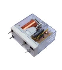
⚡ 58-12 1CO OEN Relay 5-Pin – Miniature Power Relay Module
The 58-12 1CO OEN Relay 5-Pin is a compact, high-reliability miniature power relay designed for general-purpose switching applications. Featuring a 12V DC coil and 1 changeover (1CO) contact configuration, this relay provides dependable switching for home automation, industrial control, automotive electronics, and DIY projects. With its standard 5-pin footprint and SPDT contacts rated for 10A at 250VAC, this relay offers professional performance in a space-saving package.
✨ Key Highlights
- ⚡ 12V DC Coil – Standard voltage for automotive and battery systems
- 🔄 1CO (1 Changeover) Contact – SPDT configuration with NO, NC, COM
- 🔌 10A Switching Capacity – Handle high-power loads reliably
- 📐 Compact Footprint – Space-saving miniature design
- 💡 Low Coil Power – Efficient operation at ~400mW
- 🔧 5-Pin Standard – Easy PCB mounting or socket installation
- ⚙️ Long Service Life – 100,000+ mechanical operations
- 🛡️ High Dielectric Strength – 1000VAC isolation between coil and contacts
- 🌡️ Wide Temperature Range – -40°C to +85°C operation
- 🌐 Universal Application – Suitable for AC and DC loads
📊 Technical Specifications
| Specification |
Details |
| 📋 Model Number |
58-12 (OEN Series) |
| ⚡ Coil Voltage |
12V DC (Nominal) |
| 🔋 Coil Voltage Range |
9.6V – 14.4V DC (±20%) |
| 💡 Coil Current |
~33mA (typical at 12V) |
| ⚙️ Coil Resistance |
~360Ω (±10%) |
| ⚡ Coil Power |
~400mW |
| 🔌 Contact Configuration |
1CO (1 Changeover) = SPDT (Form C) |
| 🔢 Number of Contacts |
1 changeover contact (NO + NC + COM) |
| ⚡ Contact Rating (AC) |
10A @ 250VAC (Resistive Load) |
| 🔋 Contact Rating (DC) |
10A @ 30VDC (Resistive Load) |
| 💪 Maximum Switching Voltage |
250VAC / 30VDC |
| 🔌 Maximum Switching Current |
10A (Resistive), 5A (Inductive) |
| ⚙️ Contact Material |
Silver Alloy (AgNi or AgSnO2) |
| 🔒 Contact Resistance |
≤100mΩ (initial, max) |
| ⏱️ Operating Time |
≤10ms (pickup), ≤5ms (release) |
| 🔄 Mechanical Life |
10,000,000 operations (no load) |
| ⚡ Electrical Life |
100,000 operations (rated load) |
| 🛡️ Insulation Resistance |
≥100MΩ (at 500VDC) |
| ⚡ Dielectric Strength |
1000VAC (1 minute between coil and contacts) |
| 📐 Mounting Type |
PCB through-hole or relay socket |
| 📌 Pin Pitch |
5.0mm (standard spacing) |
| 🌡️ Operating Temperature |
-40°C to +85°C |
| 💧 Humidity |
5% to 85% RH (non-condensing) |
| 📏 Dimensions (L x W x H) |
~29mm x 12.7mm x 15.7mm |
| ⚖️ Weight |
~10g |
| 🏭 Standards Compliance |
UL, TÜV, CE approved |
🔌 5-Pin Configuration & Pinout
| Pin Number |
Pin Name |
Function |
| 1 |
Coil A1 (+) |
Positive coil terminal (Connect to +12V via driver) |
| 2 |
Coil A2 (-) |
Negative coil terminal (Connect to GND) |
| 3 |
COM (Common) |
Common contact – Moving contact point |
| 4 |
NO (Normally Open) |
Normally Open contact – Closed when relay energized |
| 5 |
NC (Normally Closed) |
Normally Closed contact – Open when relay energized |
🔄 Contact States (SPDT Operation)
🎯 Perfect For
| Application |
Description |
| 🚗 Automotive Electronics |
Car accessories, fog lights, horn circuits, power windows |
| 🏠 Home Automation |
Smart switches, lighting control, appliance automation |
| 🔋 Battery Systems |
12V battery management, solar charge controllers |
| 🤖 Robotics |
Motor direction control, actuator switching |
| 🔐 Security Systems |
Alarm controls, door locks, siren activation |
| 🏭 Industrial Control |
Low-power equipment switching, pilot relays |
| 🌞 Solar/RV Applications |
12V system switching, load management |
| 💡 Lighting Control |
12V LED strips, automotive bulbs, work lights |
| 🚨 Alarm/Warning Systems |
Sirens, beacons, emergency shutoff circuits |
| 🔊 Audio Equipment |
Signal routing, speaker protection, amplifier control |
| 📡 IoT Projects |
Arduino, ESP32, Raspberry Pi controlled devices |
| 🛠️ DIY Electronics |
Hobby projects, prototyping, test equipment |
🔧 Driver Circuit Options
| Control Method |
Components Needed |
Best For |
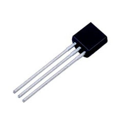
| NPN Transistor (2N2222) |
1x 2N2222, 1x 1kΩ resistor, 1x 1N4007 diode |
⭐⭐⭐ Simple, low-cost, most common |
| Darlington (TIP120) |
1x TIP120, 1x 1kΩ resistor, 1x 1N4007 diode |
⭐⭐⭐⭐ Higher current gain, 3.3V compatible |
| MOSFET (IRLZ44N) |
1x MOSFET, 1x 10kΩ resistor, 1x 1N4007 diode |
⭐⭐⭐⭐⭐ Low heat, high efficiency |
| ULN2003 IC |
1x ULN2003 (controls up to 7 relays) |
⭐⭐⭐⭐⭐ Multiple relays, built-in flyback |
| Relay Module Board |
Pre-built relay module with driver |
⭐⭐⭐⭐⭐ Easiest, beginner-friendly |
| Direct GPIO (NOT RECOMMENDED) |
None |
❌ Can damage microcontroller (33mA exceeds most pins) |
⚡ Basic Transistor Driver Circuit
| Connection |
Details |
| MCU GPIO (5V/3.3V) |
→ 1kΩ Resistor → NPN Base (2N2222 or TIP120) |
| NPN Emitter |
→ GND (Common ground) |
| NPN Collector |
→ Relay Coil Pin 2 (A2, Coil -) |
| Relay Coil Pin 1 (A1, Coil +) |
→ +12V Power Supply |
| Flyback Diode (1N4007) |
Cathode (stripe) → +12V, Anode → Coil Pin 2 (parallel to coil) |
| ⚠️ Critical Note |
Common ground between MCU and 12V supply REQUIRED |
📋 OEN Series Features
| Feature |
Description |
| 🏭 Manufacturer |
OEN (Original Equipment Number) |
| 📐 Design Type |
Miniature power relay, sealed construction |
| 🔒 Case Material |
Flame-retardant plastic (UL94V-0) |
| ⚙️ Mounting Options |
PCB through-hole, relay socket compatible |
| 🌡️ Temperature Rating |
Industrial grade (-40°C to +85°C) |
| 🔧 Termination |
Standard 5-pin configuration |
| 🛡️ Protection |
Sealed against dust and moisture (not waterproof) |
| ✅ Certifications |
UL, TÜV, CE compliant |
🔄 Load Type Derating Guide
| Load Type |
Max Current @ 12V |
Max Current @ 250VAC |
Notes |
| Resistive (Heaters, Bulbs) |
10A |
10A |
✅ Full rated current |
| LED Loads (with driver) |
10A |
10A |
✅ Low inrush, full rating OK |
| Incandescent Lamps |
6A |
6A |
⚠️ High inrush (10x), derate 40% |
| Inductive (Motors, Solenoids) |
5A |
5A |
⚠️ Derate to 50%, add suppression |
| Capacitive (Power Supplies) |
5A |
5A |
⚠️ High inrush current |
| Halogen Bulbs (12V) |
5A |
N/A |
⚠️ Very high inrush (15x) |
⚠️ Critical Safety & Usage Notes
- ⚡ 12V DC coil required – Will not operate reliably below 9.6V
- 🔌 NEVER drive directly from GPIO – 33mA exceeds most MCU pin limits
- ⚠️ ALWAYS use flyback diode – Mandatory for protecting driver circuit from back EMF
- 🔒 Observe coil polarity – Pin 1 = (+), Pin 2 = (-); non-polarized but best practice
- 💪 10A maximum per contact – Use appropriate wire gauge (16-18 AWG)
- 🔥 Inductive loads require derating – Motors/solenoids: reduce to 50% (5A max)
- ⚡ AC VOLTAGE IS DANGEROUS – 250VAC can be lethal; use qualified electrician
- 🛡️ Common ground essential – MCU GND and 12V supply GND must connect
- 🔧 Use relay socket recommended – Easy replacement without desoldering
- 🌡️ Keep within temperature limits – Avoid mounting near heat sources
- 📏 Proper spacing required – Maintain clearance between high voltage traces
- ⚠️ Not waterproof – Protect from moisture and condensation
📦 Package Contents
- ✅ 1x 58-12 OEN Relay (5-Pin, 12V DC coil)
- ✅ Standard PCB through-hole package
- ✅ Anti-static packaging
- ⚠️ Note: Driver circuit components NOT included
- ⚠️ Note: Flyback diode (1N4007) sold separately
- ⚠️ Note: Relay socket sold separately (optional)
- ⚠️ Note: 12V power supply NOT included
🔧 Example Arduino Code (Basic Control)
| Code Snippet |
// Define relay control pin (connected to transistor base)

const int RELAY_PIN = 7;
void setup() {

  pinMode(RELAY_PIN, OUTPUT);

  digitalWrite(RELAY_PIN, LOW); // Relay OFF initially

  Serial.begin(9600);

  Serial.println("58-12 Relay Control Ready");

}
void loop() {

  Serial.println("Relay ON");

  digitalWrite(RELAY_PIN, HIGH); // Energize relay

  delay(3000); // 3 seconds ON


  Serial.println("Relay OFF");

  digitalWrite(RELAY_PIN, LOW);  // De-energize relay

  delay(3000); // 3 seconds OFF

}
// Hardware: Arduino GPIO → 1kΩ → 2N2222 Base

// 2N2222 Emitter → GND

// 2N2222 Collector → Relay Coil (-)

// Relay Coil (+) → +12V

// 1N4007 Diode across coil (Cathode to +12V)
|
✅ Advantages of 58-12 OEN Relay
| Feature |
Benefit |
| 📐 Compact Size |
Miniature footprint saves PCB space |
| 💡 Low Coil Current |
33mA easy to drive with transistor/MOSFET |
| 💪 High Current Rating |
10A handles most household and automotive loads |
| 🔄 SPDT Configuration |
Versatile – can implement ON/OFF or changeover switching |
| 🏭 Industrial Quality |
UL/TÜV certified for professional applications |
| 🔒 Sealed Construction |
Protected against dust and environmental contaminants |
| 🌡️ Wide Temp Range |
-40°C to +85°C suitable for automotive and industrial use |
| 💰 Cost Effective |
Affordable solution for reliable power switching |
| 🔧 Socket Compatible |
Easy replacement without desoldering |
| ⚙️ Long Lifespan |
100,000+ operations at rated load |
🔍 Troubleshooting Guide
| Problem |
Possible Cause |
Solution |
| Relay Doesn’t Click |
Insufficient coil voltage or current |
✅ Check 12V supply, verify transistor operation, test coil resistance (~360Ω) |
| Relay Clicks But Load Doesn’t Turn On |
Wrong contact terminals used |
✅ Verify COM-NO connection (NOT COM-NC for normal operation) |
| Relay Stays Energized |
Transistor always conducting |
✅ Check GPIO signal, verify transistor not shorted |
| MCU Resets When Relay Switches |
Missing flyback diode causing voltage spike |
✅ Add 1N4007 diode across coil (cathode to +12V, anode to coil -) |
| Contacts Weld Together |
Excessive current or inrush |
✅ Reduce load current, add inrush limiting, use larger relay |
| Intermittent Operation |
Loose connections or oxidized contacts |
✅ Clean pins, check solder joints, test with multimeter |
| Relay Gets Hot |
Overcurrent through contacts |
✅ Measure load current, ensure within 10A rating |
| Short Relay Lifespan |
Switching inductive loads without protection |
✅ Add RC snubber or MOV across contacts, derate current |
🛡️ Contact Protection Circuits
| Load Type |
Protection Method |
Components |
| DC Motors/Solenoids |
Flyback Diode |
1N4007 across load (cathode to +, anode to -) |
| AC Inductive Loads |
RC Snubber |
100Ω resistor + 0.1µF/630V capacitor in series, across contacts |
| High Voltage Spikes |
MOV (Varistor) |
Metal Oxide Varistor rated 20% above supply voltage |
| Incandescent Lamps |
NTC Thermistor |
NTC inrush limiter in series with lamp |
💡 Pro Tips for Optimal Performance
- 🔧 Use relay socket – Makes replacement easy without desoldering
- 📏 Proper wire gauge – Use 18 AWG for 8-10A, 16 AWG for safety margin
- 🔌 Test before installation – Verify relay clicks and contacts switch properly
- ⚡ Add status LED – Parallel LED (with resistor) across coil shows relay state
- 🛡️ Enclosure recommended – Protect exposed contacts from accidental touch
- 🔒 Use NC contact for fail-safe – Critical loads stay ON if relay fails
- 💾 Stock spare relays – Keep replacements for critical applications
- 📋 Label connections – Document COM/NO/NC before wiring
- ⚙️ Clean contacts periodically – High-current switching can cause oxidation
- 🌡️ Monitor temperature – Excessive heat indicates overcurrent
- 🔄 Limit switching frequency – Don’t rapid-cycle relay (>1Hz sustained)
- ⚡ Add fuse protection – Always fuse the load side for safety
🔄 Alternative Relay Sockets
| Socket Type |
Mounting |
Features |
| PCB Socket |
Through-hole PCB |
✅ Direct board mounting, secure connection |
| DIN Rail Socket |
35mm DIN rail |
✅ Industrial panel mounting, easy wiring |
| Panel Mount Socket |
Screw mounting |
✅ Flexible positioning, terminal connections |
| Plug-in Socket |
Quick-connect base |
✅ Tool-free relay replacement |
🛡️ Warranty & Support
✅ Genuine OEN series relay with quality construction
✅ Factory tested for coil and contact operation
✅ Silver alloy contacts for reliable switching
✅ UL, TÜV, CE certified for safety compliance
✅ Rated for 100,000+ electrical operations
✅ Industrial temperature range (-40°C to +85°C)
✅ Standard 5-pin footprint for universal compatibility
✅ Technical datasheet and pinout diagram included
✅ Fast replacement for defective units
⚠️ Important: Always use appropriate driver circuit and flyback protection. High voltage wiring requires qualified electrician.