
Description
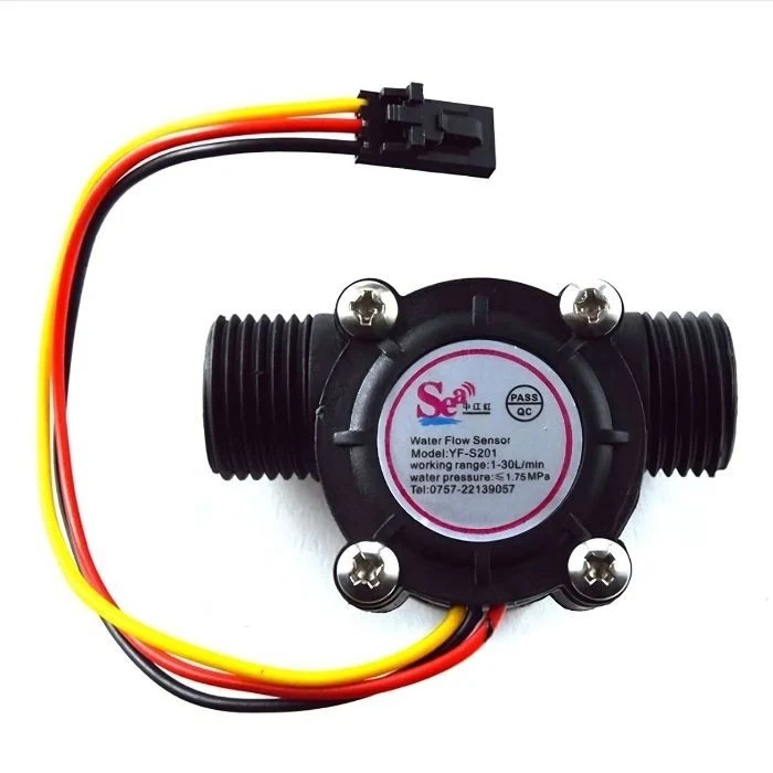
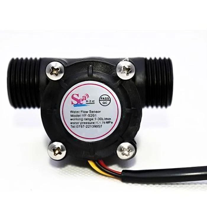
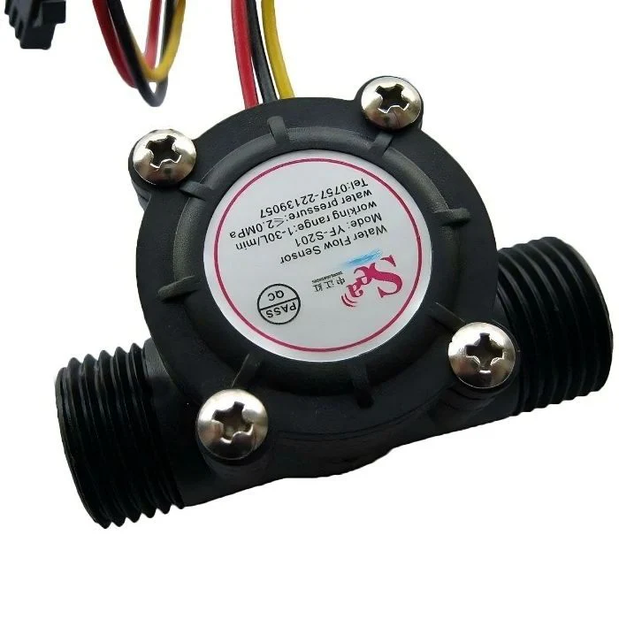
WATER FLOW SENSOR 1/2-INCH YFS201
Precision water flow sensor designed for accurate flow rate measurement and liquid consumption monitoring. The YF-S201 features a 1/2-inch threaded connection and Hall effect sensor technology for reliable, real-time flow detection. Ideal for water meters, dispensing systems, irrigation control, and automated monitoring applications where accurate flow measurement is essential.
KEY FEATURES
Hall Effect Technology – Magnetic sensing for reliable, contactless measurement
1/2-Inch Threading – Standard G1/2 thread for easy plumbing integration
Wide Flow Range – Measures flow rates from 1 to 30 liters per minute
High Accuracy – ±10% measurement precision across operating range
Food Grade Material – Safe for drinking water and food processing applications
Low Power Consumption – Operates on 5V DC with minimal current draw
Pulse Output – Digital square wave output proportional to flow rate
Temperature Resistant – Operates reliably in 0°C to 80°C water temperature
Durable Construction – Long-lasting turbine and housing design
Easy Integration – Compatible with Arduino, Raspberry Pi, ESP8266, ESP32
TECHNICAL SPECIFICATIONS
Physical Specifications:
Model Number: YF-S201 / YFS201
Thread Type: G1/2 inch (DN15) male threads both ends
Thread Standard: BSP (British Standard Pipe)
Outer Diameter: 20mm nominal bore
Overall Length: 58mm (approximately)
Body Diameter: 30mm (approximately)
Weight: 30-40 grams
Material: Food-grade plastic (POM or nylon)
Seal Material: NBR rubber O-rings
Color: Typically black or white housing
Electrical Specifications:
Operating Voltage: 5V – 24V DC (typically 5V)
Supply Current: 10-15mA (at 5V)
Output Type: NPN pulse signal (open collector)
Output Level: 0V (LOW) to VCC (HIGH)
Pulse Frequency: Proportional to flow rate
Maximum Output Current: 10mA
Wire Length: 15cm (approximately)
Wire Colors: Red (VCC), Black (GND), Yellow (Signal/Pulse)
Performance Specifications:
Flow Range: 1 – 30 L/min (liters per minute)
Optimal Range: 2 – 25 L/min
Working Pressure: ≤ 1.75 MPa (≤ 17.5 bar / 254 PSI)
Fluid Temperature: 0°C to 80°C (water)
Accuracy: ±10% (within optimal flow range)
Repeatability: ±1%
Frequency Formula: F = 7.5Q (approximately)
- F = Frequency in Hz
- Q = Flow rate in L/min
Pulse Characteristics: ~450 pulses per liter (calibration may vary)
Response Time: <1 second
Pressure Drop: Minimal (typically <0.05 MPa at 10 L/min)
Environmental Specifications:
Operating Temperature: -10°C to +60°C (ambient)
Storage Temperature: -20°C to +70°C
Humidity: 0-95% RH (non-condensing)
Protection Rating: IP65 (when properly installed)
WORKING PRINCIPLE
Hall Effect Sensor Operation:
Water flows through the sensor body causing the internal turbine/rotor to spin
Embedded magnets in the rotor pass by the Hall effect sensor
Each magnet passage generates a pulse on the output wire
Pulse frequency increases proportionally with flow rate
Microcontroller counts pulses to calculate flow rate and total volume
Pulse to Flow Calculation:
Frequency (Hz) = 7.5 × Flow Rate (L/min)
Flow Rate (L/min) = Frequency (Hz) ÷ 7.5
Pulses per Liter ≈ 450 (calibration factor may vary ±10%)
Total Volume (Liters) = Total Pulse Count ÷ 450
WIRING CONNECTIONS
Wire Color Code:
Red Wire: VCC (Power supply positive) – Connect to 5V
Black Wire: GND (Ground) – Connect to power supply ground
Yellow Wire: Signal/Pulse Output – Connect to microcontroller input pin
Connection Diagram:
Sensor → Arduino/ESP32/Raspberry Pi
Red → 5V power pin
Black → GND pin
Yellow → Digital input pin (D2, D3, or interrupt-capable pin)
Pull-up Resistor:
Some modules require 10kΩ pull-up resistor on signal line
Many microcontrollers have internal pull-up (enable in code)
External pull-up: Signal line → 10kΩ resistor → VCC
APPLICATIONS
Water Metering – Residential and commercial water consumption monitoring
Irrigation Systems – Automated watering with flow feedback control
Beverage Dispensing – Coffee machines, soda fountains, drink dispensers
Industrial Monitoring – Process water flow measurement and logging
Smart Home – IoT water usage tracking and leak detection
Aquarium Systems – Water change volume measurement and automation
Hydroponics – Nutrient solution flow monitoring and control
Washing Machines – Water intake measurement for optimal cycles
Cooling Systems – Liquid cooling flow verification
Laboratory Equipment – Precise liquid dispensing and measurement
MICROCONTROLLER INTEGRATION
Arduino Code Example:
volatile int pulseCount = 0;
float flowRate = 0.0;
float totalVolume = 0.0;
unsigned long oldTime = 0;

void setup() {
  Serial.begin(9600);
  pinMode(2, INPUT_PULLUP);
  attachInterrupt(digitalPinToInterrupt(2), pulseCounter, RISING);
  oldTime = millis();
}

void loop() {
  if ((millis() - oldTime) > 1000) {
    detachInterrupt(digitalPinToInterrupt(2));

    flowRate = (pulseCount / 7.5); // L/min
    totalVolume += (pulseCount / 450.0); // Liters

    Serial.print("Flow: ");
    Serial.print(flowRate);
    Serial.print(" L/min, Total: ");
    Serial.print(totalVolume);
    Serial.println(" L");

    pulseCount = 0;
    oldTime = millis();
    attachInterrupt(digitalPinToInterrupt(2), pulseCounter, RISING);
  }
}

void pulseCounter() {
  pulseCount++;
}
ESP32/ESP8266 Compatible:
Use hardware interrupt pins (GPIO 4, 5, 12, 13, 14, etc.)
Same interrupt logic as Arduino
WiFi capability for IoT data logging
Raspberry Pi Integration:
Use GPIO pins with interrupt capability
Python RPi.GPIO library for pulse counting
Ideal for data logging and cloud integration
CALIBRATION PROCEDURE
Factory Calibration:
Default: ~450 pulses per liter
Formula: F = 7.5Q (frequency in Hz, flow in L/min)
Variation: ±10% between individual sensors
Manual Calibration Steps:
Collect water in measured container (5-10 liters recommended)
Count total pulses during collection
Calculate: Calibration Factor = Total Pulses ÷ Volume Collected
Update code with new calibration factor
Repeat test to verify accuracy
Calibration Tips:
Calibrate at your typical operating flow rate
Use graduated cylinder or precision scale for measurement
Multiple test runs improve accuracy
Recalibrate if flow characteristics change (temperature, pressure)
INSTALLATION GUIDE
Mounting Orientation:
Can be installed horizontally or vertically
Ensure turbine can spin freely (no air bubbles trapped)
Arrow on housing indicates flow direction – MUST be observed
Vertical installation (upward flow) often provides best accuracy
Plumbing Connection:
Apply thread seal tape (PTFE/Teflon tape) to male threads
Hand-tighten first, then 1-2 turns with wrench
Do not over-tighten – may crack plastic housing
Use G1/2 female adapters, couplers, or direct connection
Install after any filters to prevent debris damage
Best Practices:
Install straight pipe sections before and after sensor (10x diameter)
Avoid installation near elbows, valves, or flow restrictions
Use inline filter upstream to protect turbine from debris
Install shut-off valves for easy maintenance and removal
Protect wiring from water exposure with waterproof connectors
Mount securely to prevent vibration
FLOW RATE VS FREQUENCY TABLE
| Flow Rate (L/min) | Frequency (Hz) | Pulses/Second |
|---|---|---|
| 1 | 7.5 | 7.5 |
| 2 | 15 | 15 |
| 5 | 37.5 | 37.5 |
| 10 | 75 | 75 |
| 15 | 112.5 | 112.5 |
| 20 | 150 | 150 |
| 25 | 187.5 | 187.5 |
| 30 | 225 | 225 |
Note: Actual values may vary ±10% due to manufacturing tolerances.
MAINTENANCE TIPS
Regular Inspection – Check for leaks at threaded connections monthly
Clean Turbine – Remove and clean turbine every 6-12 months
Debris Check – Inspect for sediment or debris blocking rotor
Seal Inspection – Check O-rings for wear or damage annually
Wiring Check – Verify wire connections remain secure and dry
Filter Maintenance – Clean upstream filter regularly
Calibration Verification – Test accuracy annually with known volume
Scale Removal – Clean calcium/mineral deposits with vinegar solution
TROUBLESHOOTING
No Pulse Output:
Check power supply (5V on red wire, GND on black wire)
Verify wiring connections are secure
Test with multimeter: yellow wire should pulse between 0V and VCC
Check if turbine spins freely (remove sensor, blow through it)
Verify microcontroller interrupt code is functioning
Inaccurate Readings:
Recalibrate sensor with known volume measurement
Check for air bubbles in system (purge air)
Verify flow direction matches arrow on housing
Ensure straight pipe runs before/after sensor
Clean turbine of debris or buildup
Check for leaks causing flow bypass
Intermittent Output:
Inspect wire connections for loose contacts
Check for water ingress in wire junction
Verify stable power supply (ripple-free 5V)
Test for electromagnetic interference near sensor
Low or No Flow Reading Despite Water Flow:
Turbine may be jammed with debris – clean thoroughly
Check if flow rate is below minimum (1 L/min)
Verify sensor is not installed backwards
Inspect for damaged turbine blades
ACCURACY FACTORS
Factors Affecting Accuracy:
Water Temperature – Viscosity changes affect turbine speed
Flow Rate – Most accurate in middle range (2-25 L/min)
Installation Orientation – Vertical upward flow often best
Pipe Turbulence – Straight runs improve accuracy
Pressure Variations – Sudden changes may cause brief errors
Debris – Particles can slow or jam turbine
Air Bubbles – Create erratic pulse patterns
Improving Accuracy:
Calibrate at operating temperature
Maintain consistent pressure
Install proper straight pipe sections
Use inline filter
Regular maintenance and cleaning
COMPARISON WITH OTHER FLOW SENSORS
vs 3/4-Inch Flow Sensors (YF-S402):
✗ Lower maximum flow rate (30 L/min vs 60 L/min)
✓ Better for smaller pipes and lower flows
✓ Lower cost
✓ More compact size
vs Ultrasonic Flow Sensors:
✗ Requires physical installation in pipe
✗ Moving parts subject to wear
✓ Much lower cost
✓ Simpler installation and integration
✓ No external power requirements beyond 5V
vs Turbine Flow Meters (Industrial):
✗ Lower accuracy (±10% vs ±1-2%)
✗ Plastic construction vs metal
✓ Significantly lower cost
✓ Adequate for most DIY and home automation needs
SAFETY PRECAUTIONS
Do not exceed maximum pressure rating (1.75 MPa)
Verify water temperature remains within 0-80°C range
Do not use with corrosive or chemically aggressive fluids
Ensure electrical connections are waterproofed
Do not use in explosive or hazardous environments
Install pressure relief if system can exceed sensor rating
Protect from freezing temperatures when water-filled
Regularly inspect for leaks and structural integrity
PACKAGE CONTENTS
1x YF-S201 Water Flow Sensor (1/2-inch)
3x Pre-attached wires (Red, Black, Yellow) – approximately 15cm
2x Rubber O-ring seals (may be pre-installed)
Installation instructions (may vary by seller)
Items Not Included (typically sold separately):
Thread seal tape (PTFE/Teflon)
Pipe adapters or fittings
Microcontroller (Arduino, ESP32, etc.)
Power supply (5V DC)
Waterproof wire connectors
Mounting hardware
WHY CHOOSE YF-S201 FLOW SENSOR?
The YF-S201 offers an excellent balance of accuracy, reliability, and affordability for water flow measurement applications. Its standard 1/2-inch threading ensures compatibility with common plumbing systems, while the Hall effect sensor technology provides maintenance-free, contactless operation. Perfect for DIY water monitoring projects, irrigation automation, and industrial process control where precise flow measurement is essential.
IDEAL USE CASES
Smart water meter for home consumption monitoring
Automated plant watering with precise volume control
Coffee machine or beverage dispenser flow measurement
Aquarium water change automation
Hydroponics nutrient delivery systems
Leak detection and early warning systems
Industrial process monitoring and logging
Solar hot water system flow verification