Description
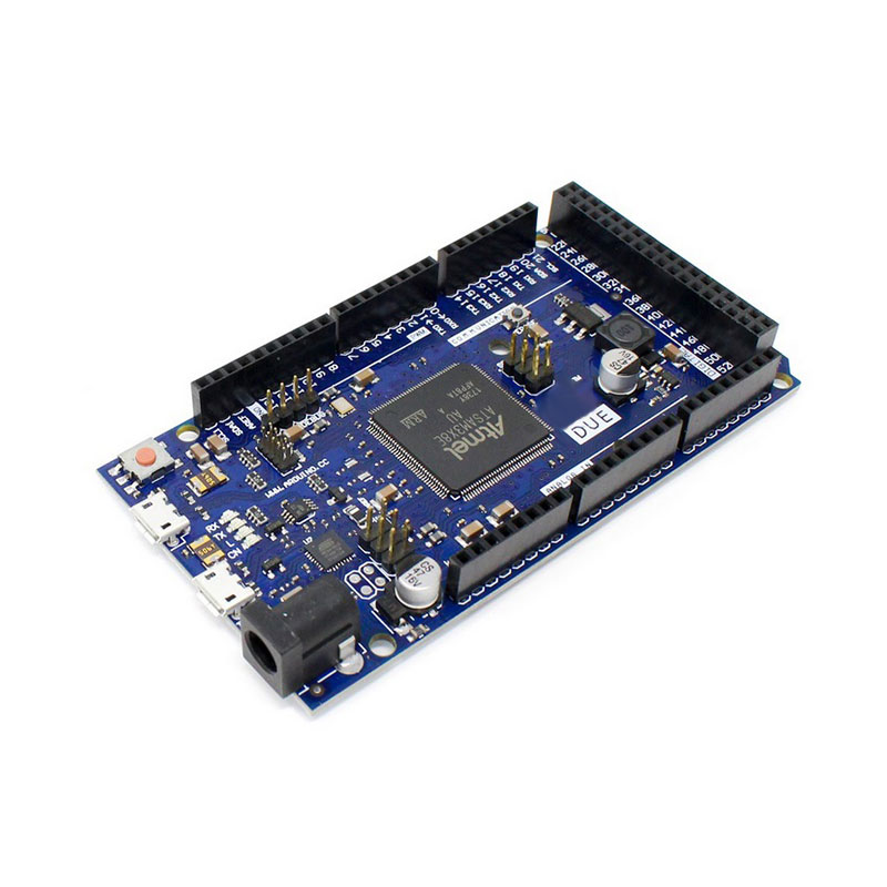
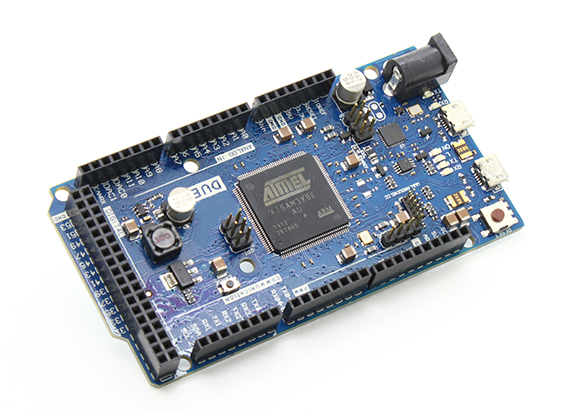
🔧 Arduino Due – SAM3X8E ARM Cortex-M3 32-Bit Development Board
The Arduino Due is Arduino’s first ARM-based microcontroller development board, featuring the powerful Atmel SAM3X8E ARM Cortex-M3 processor running at 84MHz. With 54 digital I/O pins, 12 analog inputs, 2 DAC outputs, 512KB flash memory, and native USB support, this board delivers desktop-class processing power for demanding applications. Operating at 3.3V logic, the Due is perfect for high-speed data processing, DSP applications, advanced robotics, real-time audio/video processing, and complex algorithms that exceed the capabilities of standard 8-bit Arduino boards.
✨ Key Highlights
- ⚡ 84 MHz ARM Cortex-M3 – 5x faster than standard Arduino
- 💻 32-Bit Architecture – Advanced processing capability
- 📌 54 Digital I/O Pins – Massive I/O (12 PWM)
- 📊 12 Analog Inputs – 12-bit ADC (0-4095 resolution)
- 🎵 2 DAC Outputs – True analog output (12-bit)
- 💾 512 KB Flash – 16x more than Arduino Uno
- 🧠 96 KB SRAM – 48x more RAM than Uno
- 🔌 Native USB Host/Device – USB keyboard/mouse support
- 📡 4 Hardware Serial Ports – Multiple UART communication
- ⚠️ 3.3V Logic Level – Modern low-voltage standard
📊 Technical Specifications
| 💻 Microcontroller |
AT91SAM3X8E (ARM Cortex-M3) |
| ⚡ Operating Voltage |
3.3V DC |
| 🔋 Input Voltage |
7-12V (recommended) |
| ⏱️ Clock Speed |
84 MHz |
| 💾 Flash Memory |
512 KB (all available) |
| 🧠 SRAM |
96 KB (two banks: 64KB + 32KB) |
| 📌 Digital I/O |
54 pins (12 PWM) |
| 📊 Analog Input |
12 pins (12-bit ADC) |
| 🎵 Analog Output |
2 DAC pins (12-bit) |
| 💡 DC Current per I/O |
15 mA (130 mA total) |
| 📡 Serial Ports |
4 UART (Serial 0-3) |
| 🔌 USB Ports |
2 (Programming + Native) |
| 📏 Dimensions |
101.52×53.3mm |
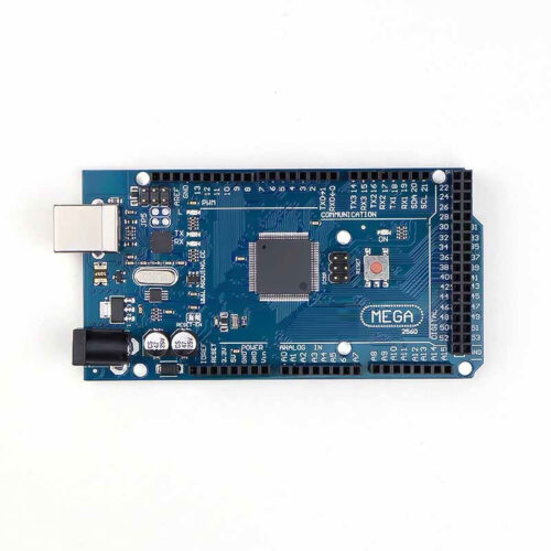
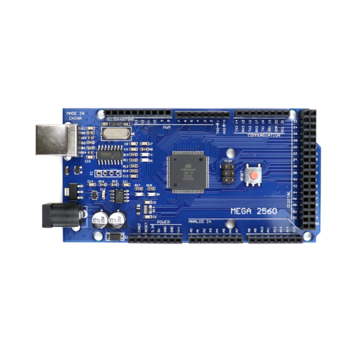
⚡ ARM Cortex-M3 vs AVR Comparison
| Feature |
Arduino Due |
Mega 2560 |
Uno R3 |
| Architecture |
32-bit ARM |
8-bit AVR |
8-bit AVR |
| Clock Speed |
84 MHz |
16 MHz |
16 MHz |
| Flash Memory |
512 KB |
256 KB |
32 KB |
| SRAM |
96 KB |
8 KB |
2 KB |
| Logic Level |
⚠️ 3.3V |
5V |
5V |
| ADC Resolution |
12-bit (4096) |
10-bit (1024) |
10-bit (1024) |
| DAC Output |
✅ 2 pins |
❌ No |
❌ No |
📌 Pin Configuration Overview
| Digital I/O |
54 pins (D0-D53, all 3.3V) |
| PWM Output |
12 pins (D2-D13) |
| Analog Input |
12 pins (A0-A11, 12-bit) |
| DAC Output |
2 pins (DAC0, DAC1) |
| Serial Ports |
Serial0-3 (4 UART) |
| I2C Bus |
SDA(D20), SCL(D21) + SDA1(D70), SCL1(D71) |
| SPI Bus |
Standard SPI + Extended SPI header |
| CAN Bus |
2 CAN channels (CANRX, CANTX) |
| USB |
Programming port + Native port |
🎯 Perfect For
- ⚡ High-Speed Processing – Fast calculations, real-time data
- 🎵 Audio Processing – DSP, synthesizers, audio effects
- 📹 Video Processing – Image manipulation, camera interfaces
- 🤖 Advanced Robotics – Complex algorithms, sensor fusion
- 🎮 USB HID Devices – Custom keyboards, mice, game controllers
- 🚗 CAN Bus Projects – Automotive diagnostics, vehicle networks
- 📊 Data Acquisition – High-resolution ADC, fast sampling
- 🔬 Scientific Instruments – Precision measurements, control systems
🔧 Getting Started
| 1. Install IDE |
Arduino IDE 1.5.0 or higher required |
| 2. Install Board |
Tools → Board → Arduino Due (Programming Port) |
| 3. Connect Cable |
Use Programming Port (near power jack) |
| 4. Select Port |
Choose correct COM/serial port |
| 5. Upload Code |
Click Upload (auto-reset supported) |
| 6. Verify |
Check Serial Monitor at 9600 baud |
✅ Key Advantages
- ⚡ 84 MHz Speed – 5x faster processing than AVR boards
- 💻 32-Bit Architecture – Handle larger numbers, complex math
- 💾 512 KB Flash – Store large programs, data tables
- 🧠 96 KB SRAM – Process large arrays, buffers
- 📊 12-Bit ADC – 4096 levels vs 1024 (4x resolution)
- 🎵 True DAC Output – Real analog audio, waveforms
- 🔌 Native USB – Act as USB host or device
- 🚗 CAN Bus Support – Automotive, industrial communication
- 📡 4 Serial Ports – Multiple simultaneous connections
- ⚙️ DMA Capability – Hardware data transfers
⚠️ Critical 3.3V Warnings
- ⚡ 3.3V LOGIC ONLY – NEVER apply 5V to any I/O pin!
- 🔥 Permanent Damage – 5V input will destroy the board instantly
- 🔌 5V Sensors – Must use level shifters or voltage dividers
- 📡 Serial Devices – Check voltage compatibility (3.3V only)
- 🛡️ No 5V Tolerance – Unlike some boards, Due has zero tolerance
- 💡 Shield Compatibility – Many 5V shields will damage Due
- 🔧 Level Shifters – Required for 5V Arduino shields/modules
- ⚠️ READ CAREFULLY – This is the most common way to break the Due
🔋 Power Supply Options
| USB Power |
5V from computer – programming & testing |
| Barrel Jack |
7-12V DC (recommended for projects) |
| VIN Pin |
7-12V direct input (regulated onboard) |
| 3.3V Pin |
Max 800mA output for sensors |
| 5V Pin |
Available but DO NOT use for logic levels |
🔌 Dual USB Ports Explained
| Programming Port |
Near power jack – use for uploading code |
| Native USB Port |
Middle – USB host/device (keyboard/mouse) |
| Programming Use |
Standard Arduino upload, Serial Monitor |
| Native USB Use |
USB HID, USB host for peripherals |
🔍 Troubleshooting
| Board Not Detected |
Use Programming Port, not Native USB port |
| Upload Failed |
Select “Arduino Due (Programming Port)” |
| Code Doesn’t Run |
Check 3.3V compatibility of all connections |
| Sensor Not Working |
Verify sensor supports 3.3V logic levels |
| Board Dead |
Check if 5V was applied to I/O pins (common) |
| Erase Flash |
Press Erase button (next to Reset) if corrupted |
💡 Pro Tips
- ⚠️ 3.3V ONLY – Triple-check all connections are 3.3V compatible
- 🔌 Use Programming Port – For normal Arduino upload operations
- 🛡️ Level Shifters – Invest in bidirectional level shifters for 5V devices
- 📡 Serial Ports – Leverage 4 UARTs for complex communication
- 🎵 DAC Pins – Use DAC0/DAC1 for audio, waveform generation
- ⚡ Speed Advantage – Optimize code for 84MHz, avoid delays
- 💾 Large Arrays – Utilize 96KB SRAM for data buffers
- 📚 ARM Libraries – Some AVR libraries may not work, use Due-compatible ones
🎵 DAC (Digital-to-Analog) Applications
- 🎵 Audio Synthesis – Generate music, tones, sound effects
- 📻 Waveform Generation – Sine, square, triangle waves
- 📡 Signal Processing – Analog output for control systems
- 🎮 Analog Joystick – Create analog voltage outputs
- 🔬 Test Equipment – Programmable voltage source
- 💡 LED Dimming – True analog brightness control
🚗 CAN Bus Capability
- 🚗 Automotive Diagnostics – Read OBD-II vehicle data
- 🏭 Industrial Automation – Factory equipment communication
- 🤖 Robot Networks – Multi-robot coordination
- ⚙️ CAN Transceiver – Requires external MCP2551 or similar chip
- 📡 Dual CAN – Two independent CAN bus channels
🔧 Compatibility Notes
- ⚠️ 5V Shields – Most standard Arduino shields NOT compatible
- ✅ 3.3V Shields – Only use shields designed for 3.3V operation
- 📚 Library Support – Most libraries work, some need ARM-specific versions
- 🔌 Sensors – Check sensor voltage (many are 3.3V compatible)
- 💾 EEPROM – Due has no built-in EEPROM (use flash emulation)
- ⚙️ Interrupts – All digital pins support interrupts (not just 2-3)
📦 Package Contents
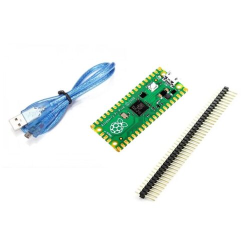
- ✅ 1x Arduino Due R3 Development Board
- ✅ 1x USB A to Micro-B Cable
- ⚠️ Note: Jumper wires, sensors sold separately
- ⚠️ Note: External power supply (7-12V) sold separately
- ⚠️ Note: Level shifters required for 5V devices (sold separately)
- ⚠️ WARNING: All peripherals MUST be 3.3V compatible!
🎓 Example Projects
- 🎵 Audio Synthesizer – Use DAC for music generation
- 📹 Video Processing – Camera interface, image manipulation
- 🚗 OBD-II Reader – Car diagnostics via CAN bus
- 🎮 USB Game Controller – Custom HID device
- 📊 Oscilloscope – High-speed ADC data acquisition
- 🤖 Advanced Robot – Sensor fusion, path planning
- 🔬 Lab Equipment – Precision measurement instruments
- 📡 SDR Receiver – Software-defined radio applications
⚡ Performance Comparison
- 🚀 Math Operations – 32-bit calculations 10-100x faster
- 📊 Float Operations – Hardware FPU for fast floating-point
- 💾 Memory Access – Faster RAM access than AVR
- ⏱️ Interrupt Latency – Lower latency, faster response
- 🔄 DMA Transfers – Background data movement without CPU
🛡️ Product Information
✅ Arduino Due – SAM3X8E ARM Cortex-M3 32-Bit Development Board
✅ 84 MHz ARM Cortex-M3 processor – 5x faster than AVR boards
✅ 32-bit architecture – advanced processing capability
✅ 512 KB flash memory, 96 KB SRAM – massive storage
✅ 54 digital I/O pins (12 PWM) + 12 analog inputs (12-bit ADC)
✅ 2 DAC outputs (12-bit) – true analog output capability
✅ 4 hardware serial ports (UART 0-3)
✅ Dual USB ports – Programming + Native USB host/device
✅ CAN bus support – 2 independent CAN channels
✅ DMA capability for efficient data transfers
✅ All digital pins support interrupts
✅ Arduino IDE compatible (1.5.0+)
⚠️ CRITICAL WARNING: 3.3V LOGIC ONLY! NEVER apply 5V to any I/O pin – this will PERMANENTLY DAMAGE the board! All sensors, shields, and modules MUST be 3.3V compatible. Use level shifters for 5V devices. Most standard Arduino 5V shields will damage the Due. Check voltage compatibility before connecting anything. Programming Port (near power jack) for code upload. Native USB Port (middle) for USB host/device. No built-in EEPROM (use flash emulation). Max 15mA per I/O pin. Requires Arduino IDE 1.5.0 or higher.