Description
📱 5V T-Relay Module – Compact Relay Board with ESP32 Integration Ready
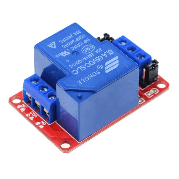
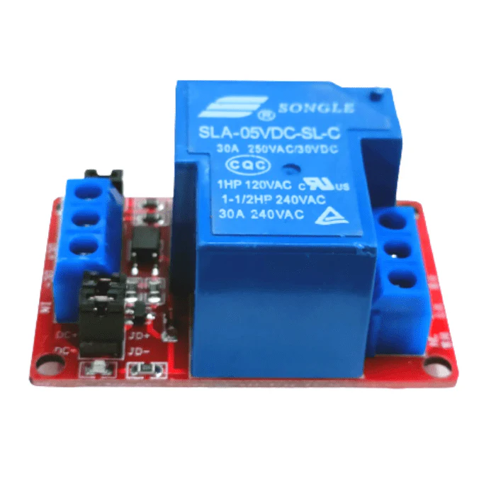
The 5V T-Relay Module is a specialized compact relay board designed for seamless integration with ESP32 development boards and 5V microcontroller systems. This professional-grade module features an onboard driver circuit, optocoupler isolation, LED indicator, and screw terminals in an ultra-compact form factor. Perfect for Arduino, ESP32, and IoT projects where space is at a premium, this module provides reliable 10A switching capability with complete electrical isolation and plug-and-play simplicity.
✨ Key Highlights
- ⚡ 5V Operation – Optimized for Arduino, ESP32, and 5V systems
- 📐 Ultra-Compact Design – Space-saving miniature form factor
- 🔒 Optocoupler Isolation – Complete electrical isolation for safety
- 🔌 10A Relay Contact – Switch high-power loads up to 250VAC/30VDC
- 💡 LED Indicator – Visual relay status feedback
- 🔧 Screw Terminals – Easy, secure wire connections
- 📱 3.3V Logic Compatible – Works with ESP8266, ESP32, Raspberry Pi
- 🛡️ Driver Circuit Built-in – No external transistors needed
- 🔄 SPDT Configuration – NO, NC, COM contacts available
- 🌐 IoT Ready – Perfect for WiFi/Bluetooth control projects
📊 Technical Specifications
| Specification |
Details |
| 🔌 Module Type |
Single-Channel 5V Relay Module (T-Relay) |
| ⚡ Operating Voltage |
5V DC |
| 🔋 Voltage Range |
4.5V – 5.5V DC |
| 💡 Control Signal Input |
3.3V – 5V compatible (optocoupler isolated) |
| 📡 Trigger Current |
~2-5mA (low current, MCU-friendly) |
| 🔋 Module Current Draw |
~70-80mA @ 5V (relay energized) |
| 🔧 Trigger Logic |
Active High (typical) or Active Low (jumper selectable) |
| 🔒 Isolation |
PC817 optocoupler (or equivalent) |
| 🔌 Relay Type |
SRD-05VDC-SL-C (SPDT) |
| ⚡ Contact Rating (AC) |
10A @ 250VAC / 10A @ 125VAC |
| 🔋 Contact Rating (DC) |
10A @ 30VDC / 10A @ 28VDC |
| 💪 Maximum Switching Power |
2500VA (AC) / 300W (DC) |
| 🔌 Contact Configuration |
SPDT (Form C) – NO, NC, COM terminals |
| 💡 LED Indicator |
Relay status LED (green/blue) |
| 🔧 Terminals |
Screw terminals for relay contacts (COM, NO, NC) |
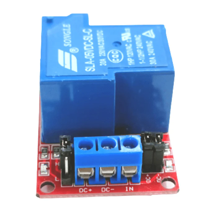
| 📌 Control Interface |
3-pin header (VCC, GND, IN) or direct wire pads |
| ⏱️ Response Time |
≤10ms (pickup), ≤5ms (release) |
| 🔄 Relay Lifespan |
100,000 operations (rated load) |
| 🌡️ Operating Temperature |
-10°C to +60°C |
| 💧 Humidity |
20% to 80% RH (non-condensing) |
| 📏 PCB Dimensions |
~35mm x 25mm x 18mm (L x W x H) – Compact! |
| ⚖️ Weight |
~10g |
| 🔩 Mounting Holes |
2x M2.5 mounting holes (2.5mm diameter) |
🔌 Terminal & Pin Configuration
| Terminal/Pin |
Function |
Connection |
| VCC (+) |
Power Input |
Connect to +5V power source (Arduino 5V, USB, PSU) |
| GND (-) |
Ground |
Connect to power supply and MCU ground |
| IN (Signal) |
Control Input |
Connect to MCU GPIO (3.3V or 5V logic) |
| COM (Common) |
Common Contact |
Connect to load or power source |
| NO (Normally Open) |
N.O. Contact |
Closed when relay energized |
| NC (Normally Closed) |
N.C. Contact |
Open when relay energized |
💡 LED Indicator Status
| LED |
Color |
Status Indication |
| Relay LED |
Green/Blue |
ON = Relay energized (contact switched) |
🎯 Perfect For
| Application |
Description |
| 📱 ESP32 IoT Projects |
WiFi/Bluetooth controlled devices, smart home automation |
| 🤖 Arduino Compact Projects |
Space-constrained automation, robot control |
| 🍓 Raspberry Pi GPIO Control |
Single-load switching from Pi GPIO pins |
| 💡 Smart Light Switches |
WiFi-controlled lighting, voice assistant integration |
| 🔌 Smart Plug Projects |
DIY smart outlet, appliance automation |
| 🏠 Compact Home Automation |
Small form factor automation nodes |
| 🌱 Plant Watering Systems |
Compact pump control, moisture sensor integration |
| 🚪 Access Control |
Electric lock control, small door strikes |
| 🔋 Battery-Powered Projects |
Low-power relay control with 5V battery packs |
| 📡 Remote Control Systems |
WiFi/Bluetooth remote switching applications |
| 🎓 Educational Projects |
Learning relay control, STEM education |
| 🔧 Prototype Development |
Quick relay integration for proof-of-concept |
📦 Package Contents
- ✅ 1x 5V T-Relay Module Board
- ✅ Pre-installed relay and optocoupler
- ✅ Screw terminals for relay contacts (COM, NO, NC)
- ✅ 3-pin control pads/header (configuration varies by version)
- ✅ LED indicator pre-installed
- ⚠️ Note: Connection wires NOT included (Dupont wires or direct solder)
- ⚠️ Note: 5V power supply NOT included
- ⚠️ Note: Mounting hardware NOT included
💻 Arduino Code Examples
Basic ON/OFF Control
| Code Snippet |
// Define relay control pin

const int RELAY_PIN = 7;
void setup() {

  pinMode(RELAY_PIN, OUTPUT);

  digitalWrite(RELAY_PIN, LOW); // Relay OFF initially

  Serial.begin(9600);

  Serial.println("5V T-Relay Ready");

}
void loop() {

  Serial.println("Relay ON");

  digitalWrite(RELAY_PIN, HIGH); // Turn relay ON

  delay(3000); // Stay ON for 3 seconds


  Serial.println("Relay OFF");

  digitalWrite(RELAY_PIN, LOW);  // Turn relay OFF

  delay(3000); // Stay OFF for 3 seconds

}
|
ESP32 WiFi Control (Minimal)
| Code Snippet |
#include <WiFi.h>

#include <WebServer.h>
const int RELAY_PIN = 16; // ESP32 GPIO16

const char* ssid = "YourWiFi";

const char* password = "YourPassword";
WebServer server(80);
void setup() {

  pinMode(RELAY_PIN, OUTPUT);

  digitalWrite(RELAY_PIN, LOW);


  WiFi.begin(ssid, password);

  while (WiFi.status() != WL_CONNECTED) delay(500);


  server.on("/on", []() {

    digitalWrite(RELAY_PIN, HIGH);

    server.send(200, "text/plain", "Relay ON");

  });


  server.on("/off", []() {

    digitalWrite(RELAY_PIN, LOW);

    server.send(200, "text/plain", "Relay OFF");

  });


  server.begin();

}
void loop() {

  server.handleClient();

}

// Access: http://[ESP32_IP]/on or /off
|
Smart Plug Example with Timer
| Code Snippet |
const int RELAY_PIN = 7;

const unsigned long TIMEOUT = 30000; // 30 seconds max ON time
unsigned long relayOnTime = 0;

bool relayState = false;
void setup() {

  pinMode(RELAY_PIN, OUTPUT);

  digitalWrite(RELAY_PIN, LOW);

  Serial.begin(9600);

}
void turnRelayOn() {

  digitalWrite(RELAY_PIN, HIGH);

  relayState = true;

  relayOnTime = millis();

  Serial.println("Relay ON - Timer started");

}
void turnRelayOff() {

  digitalWrite(RELAY_PIN, LOW);

  relayState = false;

  Serial.println("Relay OFF");

}
void loop() {

  // Auto-shutoff after timeout

  if (relayState && (millis() - relayOnTime > TIMEOUT)) {

    turnRelayOff();

    Serial.println("Auto-shutoff: Timeout reached");

  }


  // Your control logic here

  // Example: button press, serial command, etc.

}
|
✅ Advantages of 5V T-Relay Module
| Feature |
Benefit |
| 📐 Ultra-Compact Size |
~35x25mm – fits tight spaces, ideal for small enclosures |
| ⚡ 5V Optimized |
Perfect voltage for Arduino, ESP32, USB power projects |
| 🔒 Optocoupler Protection |
Isolated control prevents MCU damage from load spikes |
| 💡 Low Trigger Current |
2-5mA won’t overload GPIO pins |
| 💪 Full 10A Rating |
Despite compact size, handles high-power loads |
| 🔧 Easy Integration |
Plug-and-play with popular dev boards |
| 🛡️ Professional Build |
Quality PCB with proper isolation and protection |
| 📱 IoT Ready |
3.3V logic compatible for ESP8266/ESP32 |
| 💰 Cost Effective |
Affordable solution for single-load control |
| ⚙️ SPDT Flexibility |
NO/NC contacts provide versatile switching options |
⚠️ Important Safety & Usage Notes
- ⚡ 5V power required – Module designed specifically for 5V operation
- 🔌 Common ground essential – Module GND and MCU GND must connect
- ⚠️ AC VOLTAGE IS DANGEROUS – 250VAC can be lethal; hire qualified electrician
- 🔒 Compact size = heat concentration – Ensure adequate ventilation
- 💪 10A maximum load – Use appropriate wire gauge (16-18 AWG)
- 🔥 Inductive loads require derating – Motors/solenoids 50% reduction (5A max)
- 🛡️ Optocoupler provides isolation – But still use proper enclosure
- 📏 Small mounting holes – M2.5 screws required, handle carefully
- 🌡️ Monitor temperature – Compact design may run warm under heavy loads
- 🔧 Secure screw terminals – Small terminals need careful tightening
- ⚡ Add fuse protection – Always fuse the load circuit
- 📱 Test before deployment – Verify operation with multimeter first
🔍 Troubleshooting Guide
| Problem |
Possible Cause |
Solution |
| Relay Won’t Switch |
Insufficient 5V power or no signal |
✅ Verify 5V supply, check GPIO output with multimeter |
| LED On But Load Doesn’t Work |
Incorrect COM-NO/NC wiring |
✅ Verify COM-NO connection, test contacts with multimeter |
| Relay Clicks But Doesn’t Stay On |
Power supply can’t provide enough current |
✅ Use PSU with min 500mA capacity, check voltage under load |
| ESP32/ESP8266 Won’t Trigger |
3.3V signal borderline for optocoupler |
✅ Should work – verify connections, try different GPIO pin |
| Module Gets Very Hot |
Overcurrent through relay or poor ventilation |
✅ Reduce load current, ensure airflow, check for short circuit |
| Inverted Operation |
Active Low mode (if jumper exists) |
✅ Check for trigger mode jumper, invert logic in code |
| Intermittent Operation |
Loose wire connections or cold solder joint |
✅ Check all connections, resolder if necessary |
| Arduino Resets When Switching |
Voltage drop from relay inrush current |
✅ Add 100µF capacitor across VCC/GND, use external 5V PSU |
💡 Pro Tips for T-Relay Projects
- 🔧 Use USB power banks – Portable 5V power for mobile projects
- 📏 Keep wires short – Compact module benefits from tidy wiring
- ⚡ Separate power for high loads – Don’t power Arduino and relay from same USB
- 🛡️ 3D printed enclosures – Small size perfect for custom housings
- 💾 MQTT for IoT – More reliable than HTTP for smart home integration
- 📋 Label connections – Small board makes troubleshooting harder later
- 🔒 Add manual override – Physical button for local control
- ⏰ Implement timeouts – Safety shutoff for unattended operation
- 🌐 OTA updates – Program ESP32 wirelessly after installation
- 📱 Mobile dashboard – Create simple web interface for control
- 🔋 Power monitoring – Track on/off times and usage patterns
- 🔧 Heat sink optional – Small copper plate can help with continuous high loads
🆚 Compact Relay Comparison
| Feature |
5V T-Relay |
Standard 1CH Module |
| Size |
~35x25mm (Compact) |
~50x38mm (Standard) |
| Voltage |
5V only |
5V or 12V selectable |
| Power LED |
⚠️ May not include |
✅ Usually included |
| Mounting |
M2.5 holes |
M3 holes |
| Best For |
Space-constrained projects |
General-purpose use |
| IoT Integration |
⭐⭐⭐⭐⭐ Excellent |
⭐⭐⭐⭐ Very Good |
| Price |
💰💰 Moderate |
💰 Lower |
🏠 ESP32 Smart Home Integration
| Platform |
Integration Method |
Difficulty |
| ESPHome |
YAML configuration file |
⭐⭐ Easy |
| Home Assistant |
MQTT or ESPHome |
⭐⭐⭐ Moderate |
| Blynk IoT |
Blynk library + app |
⭐⭐ Easy |
| Google Home |
Via Home Assistant bridge |
⭐⭐⭐⭐ Advanced |
| Amazon Alexa |
Via MQTT + Node-RED |
⭐⭐⭐⭐ Advanced |
| Custom Web Interface |
ESP32 WebServer library |
⭐⭐⭐ Moderate |
🔌 Power Supply Options
| Power Source |
Capacity Needed |
Use Case |
| Arduino 5V Pin |
Limited (~500mA total) |
⚠️ Low-power loads only, not recommended for 10A switching |
| USB Power (Phone Charger) |
1A – 2A typical |
✅ Good for most projects, portable |
| USB Power Bank |
2A typical |
✅ Excellent for portable/mobile projects |
| 5V Wall Adapter |
2A recommended |
✅ Best for permanent installations |
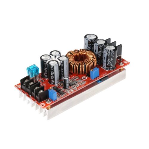
| Buck Converter (12V→5V) |
2A output |
✅ Use with 12V battery systems |
| 5V Power Supply Module |
3A or higher |
✅ Professional installations, multiple devices |
🎓 Example Projects
| Project |
Description |
Components Needed |
| WiFi Smart Switch |
Control lamp via smartphone |
ESP32, 5V T-Relay, 5V PSU, enclosure |
| Voice-Controlled Outlet |
Alexa/Google Home integration |
ESP32, relay, Home Assistant setup |
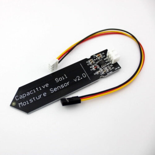
| Automated Plant Watering |
Moisture sensor triggers pump |
Arduino, relay, moisture sensor, pump |
| Smart Doorbell |
WiFi notification + door release |
ESP32, relay, button, electric strike |
| Garage Door Opener |
Remote WiFi control |
ESP32, relay, reed switch (status) |
| Arduino Timer Switch |
Time-based ON/OFF control |
Arduino, relay, RTC module, display |
🛡️ Warranty & Support
✅ Compact 5V T-Relay module with driver circuit
✅ Optocoupler isolation for safety (PC817)
✅ High-quality 10A relay (SRD-05VDC-SL-C)
✅ LED indicator for status monitoring
✅ Professional screw terminals for relay contacts
✅ Compatible with Arduino, ESP32, ESP8266, Raspberry Pi
✅ Ultra-compact design (~35x25mm)
✅ 3.3V and 5V logic compatible
✅ Pre-tested before shipping
✅ Technical documentation and wiring examples
✅ Fast replacement for defective units
⚠️ Important: High voltage AC wiring must be performed by qualified electrician. Always disconnect power before wiring. Use appropriate 5V power supply with sufficient current capacity (min 500mA). Despite compact size, this relay can switch 10A – ensure proper wire gauge and ventilation. Use appropriate enclosures for safety.