Description
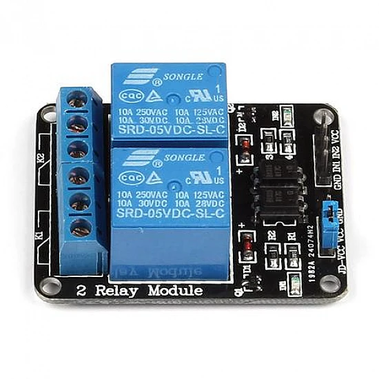
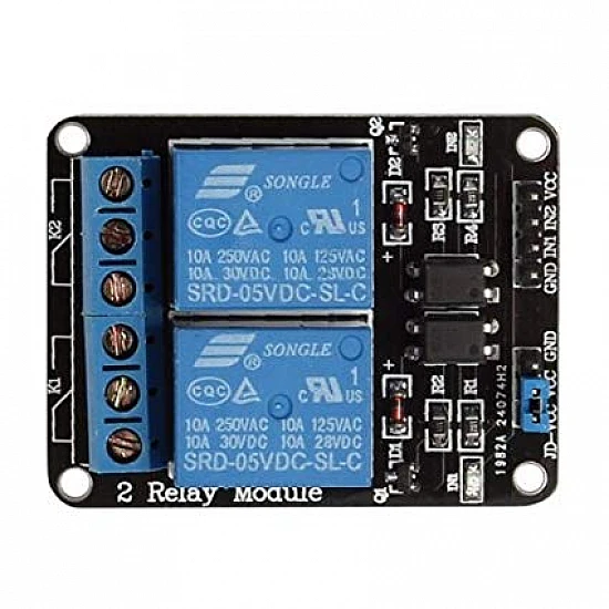
🔌 2-Channel 5V/12V Relay Module – Dual Driver Board with Optocoupler Isolation
The 2-Channel 5V/12V Relay Module is a professional dual-relay control board featuring built-in driver circuits, optocoupler isolation, LED indicators, and screw terminals. This plug-and-play module allows simultaneous control of two independent loads, making it perfect for Arduino, Raspberry Pi, ESP32, and microcontroller projects. With dual voltage support (5V or 12V) and complete electrical isolation, this module provides safe, reliable switching for home automation, IoT projects, and industrial control applications requiring multiple outputs.
✨ Key Highlights
- ⚡ Dual Independent Relays – Control two separate loads simultaneously
- 🔋 Dual Voltage Support – Works with 5V or 12V input (jumper selectable)
- 🔒 Optocoupler Isolation – Complete electrical isolation per channel
- 🔌 10A Per Channel – Each relay rated 250VAC/30VDC @ 10A
- 💡 4x LED Indicators – Power LED + status LED for each relay
- 🔧 Screw Terminals – Easy, secure wire connections for all contacts
- 📱 3.3V Logic Compatible – Works with ESP8266, ESP32, Raspberry Pi
- 🛡️ Driver Circuits Built-in – No external components needed
- 🔄 Independent Control – Each relay operates separately
- 📐 Compact PCB Design – Professional board with mounting holes
📊 Technical Specifications
| Specification |
Details |
| 🔌 Module Type |
2-Channel Relay Module Board |
| 🔢 Number of Relays |
2 independent channels |
| ⚡ Operating Voltage |
5V DC or 12V DC (jumper selectable per channel) |
| 🔋 Voltage Range |
4.5-5.5V (5V mode) / 10.8-14.4V (12V mode) |
| 💡 Control Signal Input |
3.3V – 5V compatible (optocoupler isolated) |
| 📡 Trigger Current |
~2-5mA per channel (low current, MCU-friendly) |
| 🔧 Trigger Logic |
Active High or Active Low (jumper selectable per channel) |
| 🔒 Isolation |
PC817 optocoupler per channel |
| 🔌 Relay Type |
SRD-05VDC-SL-C or SRD-12VDC-SL-C (SPDT) x2 |
| ⚡ Contact Rating (AC) |
10A @ 250VAC / 10A @ 125VAC per channel |
| 🔋 Contact Rating (DC) |
10A @ 30VDC / 10A @ 28VDC per channel |
| 💪 Maximum Switching Power |
2500VA (AC) / 300W (DC) per channel |
| 🔌 Contact Configuration |
SPDT (Form C) x2 – Each has NO, NC, COM terminals |
| 💡 LED Indicators |
1x Power LED (red), 2x Relay Status LEDs (green/blue) |
| 🔧 Terminals |
Screw terminals for power and all relay contacts |
| 📌 Control Interface |
4-pin header (VCC, GND, IN1, IN2) |
| ⏱️ Response Time |
≤10ms (pickup), ≤5ms (release) per relay |
| 🔄 Relay Lifespan |
100,000 operations (rated load) per relay |
| 🌡️ Operating Temperature |
-10°C to +60°C |
| 💧 Humidity |
20% to 80% RH (non-condensing) |
| 📏 PCB Dimensions |
~51mm x 39mm x 19mm (L x W x H) |
| ⚖️ Weight |
~25g |
| 🔩 Mounting Holes |
4x M3 mounting holes (3mm diameter) |
🔌 Terminal & Pin Configuration
| Terminal/Pin |
Function |
Connection |
| VCC (DC+) |
Power Input |
Connect to +5V or +12V power supply |
| GND (DC-) |
Ground |
Connect to power supply ground |
| IN1 (CH1) |
Relay 1 Control |
Connect to MCU GPIO #1 (3.3V or 5V) |
| IN2 (CH2) |
Relay 2 Control |
Connect to MCU GPIO #2 (3.3V or 5V) |
| Relay 1 COM |
Common Contact 1 |
Connect to load 1 or power source |
| Relay 1 NO |
N.O. Contact 1 |
Closed when relay 1 energized |
| Relay 1 NC |
N.C. Contact 1 |
Open when relay 1 energized |
| Relay 2 COM |
Common Contact 2 |
Connect to load 2 or power source |
| Relay 2 NO |
N.O. Contact 2 |
Closed when relay 2 energized |
| Relay 2 NC |
N.C. Contact 2 |
Open when relay 2 energized |
🔄 Trigger Mode Configuration
| Relay |
Jumper Position |
Trigger Mode |
Behavior |
| Relay 1 |
High Level (H) |
Active High |
Relay ON when IN1 = HIGH, OFF when IN1 = LOW |
| Low Level (L) |
Active Low |
Relay ON when IN1 = LOW, OFF when IN1 = HIGH |
| Relay 2 |
High Level (H) |
Active High |
Relay ON when IN2 = HIGH, OFF when IN2 = LOW |
| Low Level (L) |
Active Low |
Relay ON when IN2 = LOW, OFF when IN2 = HIGH |
💡 LED Indicator Status
| LED |
Color |
Status Indication |
| Power LED |
Red |
ON = Module powered correctly |
| Relay 1 LED |
Green/Blue |
ON = Relay 1 energized (contact switched) |
| Relay 2 LED |
Green/Blue |
ON = Relay 2 energized (contact switched) |
🎯 Perfect For
| Application |
Description |
| 🏠 Multi-Room Lighting |
Control lights in 2 rooms independently, scene automation |
| 🌡️ HVAC Control |
Separate control of heater and fan, thermostat projects |
| 🌱 Garden Automation |
Irrigation zones, pump + valve control, grow light timers |
| 🚪 Dual Access Control |
Two doors, gate + garage, dual lock systems |
| 🤖 Robot Control |
Dual motor control, left/right motors, actuators |
| 📱 IoT Smart Home |
WiFi-controlled appliances, dual device automation |
| 💡 Light + Fan Combo |
Bathroom fan with light, bedroom light + ceiling fan |
| 🔋 Power Management |
Dual load switching, battery charger control, backup power |
| 🚨 Alarm Systems |
Siren + strobe light, dual zone activation |
| 🏭 Industrial Monitoring |
Dual equipment control, process automation |
| 🔊 Audio/Video |
Amplifier + speakers, dual source switching |
| ⚡ Dual Power Sources |
Main + backup power, redundant supply switching |
🔧 Common Wiring Configurations
| Configuration |
Setup |
Use Case |
| Two Independent Loads |
Each COM-NO controls separate device |
Two lights, two fans, two appliances |
| Sequential Operation |
Relay 1 ON → wait → Relay 2 ON |
Staged startup, motor soft-start |
| Interlocked Relays |
Only one relay active at a time (code) |
Reversing applications, mode selection |
| Redundant Switching |
Both relays control same load (parallel) |
Critical systems requiring backup relay |
| Load Sharing |
Both relays switch portions of load |
Split high-current loads across relays |
| A/B Source Selection |
Relay 1 = Source A, Relay 2 = Source B |
Dual power supply switching, antenna selection |
📦 Package Contents
- ✅ 1x 2-Channel Relay Module Board (5V/12V compatible)
- ✅ 2x Pre-installed relays with optocouplers
- ✅ Screw terminals for power and all relay contacts
- ✅ 4-pin control header (may require male-to-female jumper wires)
- ✅ 3x LED indicators pre-installed (power + 2x relay status)
- ⚠️ Note: Jumper wires NOT included (Dupont wires recommended)
- ⚠️ Note: 5V/12V power supply NOT included
- ⚠️ Note: Mounting screws NOT included
💻 Arduino Code Examples
Basic Independent Control (Active High)
| Code Snippet |
// Define relay control pins

const int RELAY1_PIN = 7;

const int RELAY2_PIN = 8;
void setup() {

  pinMode(RELAY1_PIN, OUTPUT);

  pinMode(RELAY2_PIN, OUTPUT);

  digitalWrite(RELAY1_PIN, LOW); // Relay 1 OFF

  digitalWrite(RELAY2_PIN, LOW); // Relay 2 OFF

  Serial.begin(9600);

  Serial.println("2-Channel Relay Ready");

}
void loop() {

  // Turn ON Relay 1

  Serial.println("Relay 1 ON");

  digitalWrite(RELAY1_PIN, HIGH);

  delay(2000);


  // Turn ON Relay 2 (both now ON)

  Serial.println("Relay 2 ON");

  digitalWrite(RELAY2_PIN, HIGH);

  delay(2000);


  // Turn OFF Relay 1

  Serial.println("Relay 1 OFF");

  digitalWrite(RELAY1_PIN, LOW);

  delay(2000);


  // Turn OFF Relay 2

  Serial.println("Relay 2 OFF");

  digitalWrite(RELAY2_PIN, LOW);

  delay(2000);

}
|
Sequential Startup (Staged Operation)
| Code Snippet |
const int RELAY1_PIN = 7; // Primary device

const int RELAY2_PIN = 8; // Secondary device
void setup() {

  pinMode(RELAY1_PIN, OUTPUT);

  pinMode(RELAY2_PIN, OUTPUT);

  digitalWrite(RELAY1_PIN, LOW);

  digitalWrite(RELAY2_PIN, LOW);

}
void startupSequence() {

  // Start primary device first

  digitalWrite(RELAY1_PIN, HIGH);

  delay(1000); // Wait 1 second


  // Start secondary device

  digitalWrite(RELAY2_PIN, HIGH);

}
void shutdownSequence() {

  // Shutdown in reverse order

  digitalWrite(RELAY2_PIN, LOW);

  delay(1000);

  digitalWrite(RELAY1_PIN, LOW);

}
void loop() {

  startupSequence();

  delay(10000); // Run for 10 seconds

  shutdownSequence();

  delay(5000); // Wait 5 seconds before restart

}
|
ESP32 WiFi Dual Control
| Code Snippet |
#include <WiFi.h>

#include <WebServer.h>
const int RELAY1_PIN = 16; // GPIO16

const int RELAY2_PIN = 17; // GPIO17

const char* ssid = "YourWiFi";

const char* password = "YourPassword";
WebServer server(80);
void setup() {

  pinMode(RELAY1_PIN, OUTPUT);

  pinMode(RELAY2_PIN, OUTPUT);

  digitalWrite(RELAY1_PIN, LOW);

  digitalWrite(RELAY2_PIN, LOW);


  WiFi.begin(ssid, password);

  while (WiFi.status() != WL_CONNECTED) delay(500);


  // Relay 1 control

  server.on("/relay1/on", []() {

    digitalWrite(RELAY1_PIN, HIGH);

    server.send(200, "text/plain", "Relay 1 ON");

  });

  server.on("/relay1/off", []() {

    digitalWrite(RELAY1_PIN, LOW);

    server.send(200, "text/plain", "Relay 1 OFF");

  });


  // Relay 2 control

  server.on("/relay2/on", []() {

    digitalWrite(RELAY2_PIN, HIGH);

    server.send(200, "text/plain", "Relay 2 ON");

  });

  server.on("/relay2/off", []() {

    digitalWrite(RELAY2_PIN, LOW);

    server.send(200, "text/plain", "Relay 2 OFF");

  });


  server.begin();

}
void loop() {

  server.handleClient();

}
|
✅ Advantages of 2-Channel Module
| Feature |
Benefit |
| 🔄 Dual Independent Control |
Control two loads separately with one board |
| 📐 Space Efficient |
Smaller than two separate 1-channel modules |
| 💰 Cost Effective |
More economical than buying two single-channel modules |
| 🔌 Simplified Wiring |
Single power connection for both relays |
| 🔒 Dual Optocoupler Isolation |
Each channel independently isolated for safety |
| 💡 Individual LED Indicators |
Visual status for each relay independently |
| ⚡ Full 10A Per Channel |
Both relays can handle 10A simultaneously |
| 🔧 Flexible Configuration |
Mix Active High/Low per channel as needed |
| 🌐 IoT Ready |
Perfect for multi-zone smart home control |
| 🛡️ Professional Build |
Quality PCB with proper isolation and protection |
⚠️ Important Safety & Usage Notes
- ⚡ Select correct voltage – Use 5V for Arduino/ESP32, 12V for automotive
- 🔌 Common ground required – Module GND and MCU GND must connect
- ⚠️ AC VOLTAGE IS DANGEROUS – 250VAC can be lethal; hire qualified electrician
- 🔒 Check jumper settings – Verify Active High/Low for each channel before connecting
- 💪 10A maximum per channel – Don’t exceed 10A per relay
- 🔥 Total module current – Consider heat with both relays at high loads
- 🛡️ Independent operation – Channels don’t interfere, but share power supply
- 📏 Separate AC wiring – Keep high voltage traces isolated from each other
- 🌡️ Adequate ventilation – Module generates heat with dual loads
- 🔧 Secure all connections – Double-check all screw terminal tightness
- ⚡ Individual fusing – Use separate fuse for each load circuit
- 📱 Test channels independently – Verify each relay operates correctly
🔍 Troubleshooting Guide
| Problem |
Possible Cause |
Solution |
| Only One Relay Works |
One channel damaged or wrong wiring |
✅ Test each IN pin separately, check jumper settings |
| Both Relays Switch Together |
GPIO pins shorted or wrong code |
✅ Verify IN1 and IN2 use different GPIO pins |
| Power LED On, Relays Don’t Work |
Control signal issue or damaged optocouplers |
✅ Check IN1/IN2 signals with multimeter, verify jumpers |
| Relay LED On, Load Doesn’t Work |
Incorrect COM-NO/NC wiring |
✅ Verify load connected to correct relay (1 vs 2) |
| Intermittent Operation |
Insufficient power supply current |
✅ Use PSU with min 1A (5V) or 500mA (12V) capacity |
| Module Resets Randomly |
Voltage drop when relays switch |
✅ Add 470µF capacitor across VCC/GND, use regulated PSU |
| One Relay Always On |
Welded contacts or wrong trigger mode |
✅ Check trigger jumper (H/L), test relay with multimeter |
| ESP32/ESP8266 Won’t Trigger |
3.3V signal may be borderline |
✅ Should work – verify optocoupler, try different GPIO pins |
💡 Pro Tips for Dual Relay Projects
- 🔧 Label relay terminals – Mark Relay 1 and Relay 2 on enclosure
- 📏 Color-code wiring – Different colors for each relay circuit
- ⚡ Add external status LEDs – Visible indicators outside enclosure
- 🛡️ Use separate enclosures – If switching high-power AC loads
- 💾 Implement interlock logic – Prevent both ON when inappropriate
- 📋 Create wiring diagram – Document all connections clearly
- 🔒 Priority shutdown – Define which relay turns off first in emergency
- ⏰ Add time delays – Prevent rapid switching, extend relay life
- 🌐 MQTT state reporting – Send status updates for both channels
- 📱 Create status webpage – Display both relay states on one page
- 🔋 Power supply sizing – Account for both relay coils (~80mA @ 5V)
- 🔧 Test failure modes – Verify behavior when one relay fails
🆚 1-Channel vs 2-Channel Comparison
| Feature |
1-Channel |
2-Channel |
| Number of Loads |
1 device |
2 independent devices |
| GPIO Pins Used |
1 pin |
2 pins |
| Board Size |
~50x38mm |
~51x39mm (slightly larger) |
| Power Consumption |
~40mA @ 5V |
~80mA @ 5V (both on) |
| Complexity |
⭐ Simple |
⭐⭐ Moderate |
| Cost |
💰 Lower |
💰💰 ~50% more than single |
| vs Two Separate Modules |
N/A |
✅ More compact, easier wiring |
| Best For |
Single load control |
Multi-zone, dual device control |
🌐 Smart Home Integration Examples
| Platform |
Relay 1 Control |
Relay 2 Control |
| Home Assistant |
switch.living_room_light |
switch.living_room_fan |
| Google Home |
“Turn on bedroom light” |
“Turn on bedroom fan” |
| Amazon Alexa |
“Alexa, turn on kitchen light” |
“Alexa, turn on kitchen exhaust” |
| MQTT Topic |
home/relay/channel1/set |
home/relay/channel2/set |
| Blynk App |
Virtual Pin V1 (Button) |
Virtual Pin V2 (Button) |
🛡️ Warranty & Support
✅ Complete 2-channel relay module with dual driver circuits
✅ Dual optocoupler isolation for safety (2x PC817)
✅ High-quality 10A relays per channel (SRD series)
✅ Individual LED indicators for each relay + power
✅ Professional screw terminals for all connections
✅ Compatible with Arduino, Raspberry Pi, ESP32, ESP8266
✅ Dual voltage support (5V/12V selectable)
✅ Independent trigger mode configuration per channel
✅ Pre-tested both channels before shipping
✅ Technical documentation and example code included
✅ Fast replacement for defective units
⚠️ Important: High voltage AC wiring must be performed by qualified electrician. Always disconnect power before wiring. Each relay can handle 10A, but consider total module heat dissipation. Use appropriate enclosures for safety.