Description
🔌 1-Channel 5V/12V Relay Module – Complete Driver Board with Optocoupler Isolation
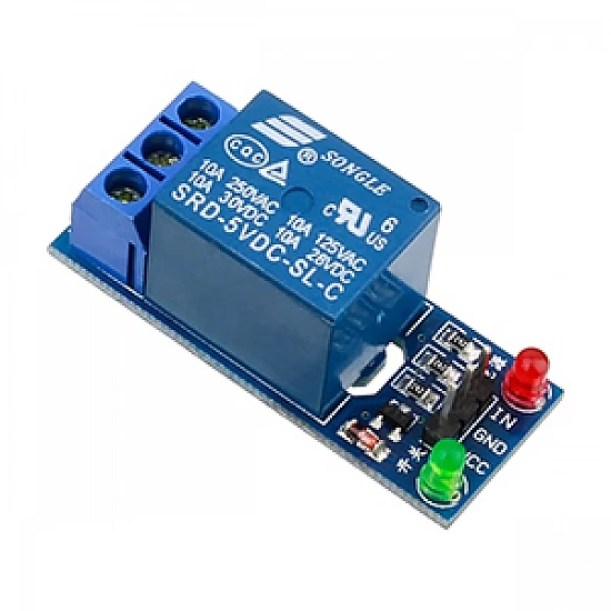
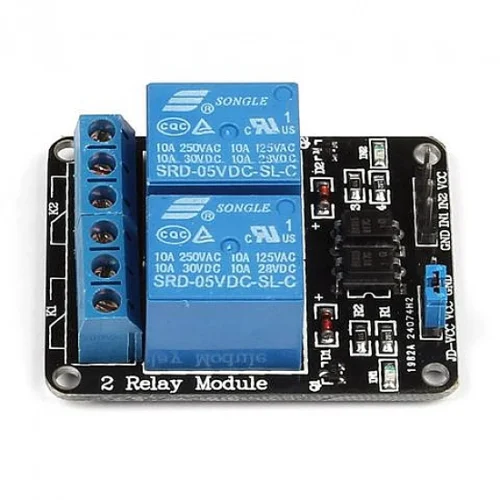
The 1-Channel 5V/12V Relay Module is a fully integrated relay control board featuring an onboard driver circuit, optocoupler isolation, LED indicators, and screw terminals. This plug-and-play module eliminates the need for external components, making it perfect for Arduino, Raspberry Pi, ESP32, and microcontroller projects. With dual voltage support (5V or 12V) and complete electrical isolation, this module provides safe, reliable switching for home automation, IoT projects, and industrial control applications.
✨ Key Highlights
- ⚡ Dual Voltage Support – Works with 5V or 12V input (jumper selectable)
- 🔒 Optocoupler Isolation – Complete electrical isolation for safety
- 🔌 10A Relay Contact – Switch high-power loads up to 250VAC/30VDC
- 💡 LED Indicators – Power LED and relay status LED included
- 🔧 Screw Terminals – Easy, secure wire connections
- 📱 3.3V Logic Compatible – Works with ESP8266, ESP32, Raspberry Pi
- 🛡️ Driver Circuit Built-in – No external transistors or MOSFETs needed
- 🔄 Active High/Low Selectable – Jumper configurable trigger logic
- 📐 Compact PCB Design – Professional board with mounting holes
- 🌐 Plug and Play – Ready to use with microcontrollers
📊 Technical Specifications
| Specification |
Details |
| 🔌 Module Type |
1-Channel Relay Module Board |
| ⚡ Operating Voltage |
5V DC or 12V DC (jumper selectable) |
| 🔋 Voltage Range |
4.5-5.5V (5V mode) / 10.8-14.4V (12V mode) |
| 💡 Control Signal Input |
3.3V – 5V compatible (optocoupler isolated) |
| 📡 Trigger Current |
~2-5mA (low current, MCU-friendly) |
| 🔧 Trigger Logic |
Active High or Active Low (jumper selectable) |
| 🔒 Isolation |
Optocoupler (PC817 or equivalent) |
| 🔌 Relay Type |
SRD-05VDC-SL-C or SRD-12VDC-SL-C (SPDT) |
| ⚡ Contact Rating (AC) |
10A @ 250VAC / 10A @ 125VAC |
| 🔋 Contact Rating (DC) |
10A @ 30VDC / 10A @ 28VDC |
| 💪 Maximum Switching Power |
2500VA (AC) / 300W (DC) |
| 🔌 Contact Configuration |
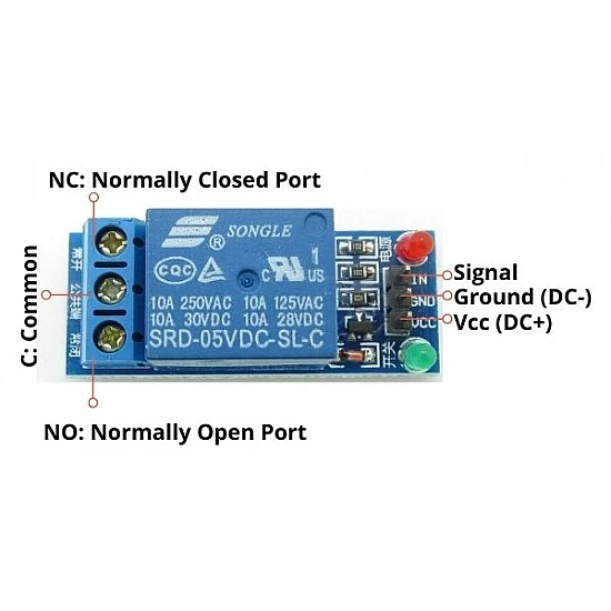
SPDT (Form C) – NO, NC, COM terminals |
| 💡 LED Indicators |
Power LED (red), Relay Status LED (green/blue) |
| 🔧 Terminals |
Screw terminals for power and relay contacts |
| 📌 Control Interface |
3-pin header (VCC, GND, IN) |
| ⏱️ Response Time |
≤10ms (pickup), ≤5ms (release) |
| 🔄 Relay Lifespan |
100,000 operations (rated load) |
| 🌡️ Operating Temperature |
-10°C to +60°C |
| 💧 Humidity |
20% to 80% RH (non-condensing) |
| 📏 PCB Dimensions |
~50mm x 38mm x 19mm (L x W x H) |
| ⚖️ Weight |
~15g |
| 🔩 Mounting Holes |
2x M3 mounting holes (3mm diameter) |
🔌 Terminal & Pin Configuration
| Terminal/Pin |
Function |
Connection |
| VCC |
Power Input |
Connect to +5V or +12V power supply |
| GND |
Ground |
Connect to power supply ground |
| IN (Signal) |
Control Input |
Connect to MCU GPIO (3.3V or 5V) |
| COM (Common) |
Common Contact |
Connect to load or power source |
| NO (Normally Open) |
N.O. Contact |
Closed when relay energized |
| NC (Normally Closed) |
N.C. Contact |
Open when relay energized |
🔄 Trigger Mode Configuration
| Jumper Position |
Trigger Mode |
Behavior |
| High Level (H) |
Active High |
Relay ON when IN = HIGH (3.3V/5V), OFF when IN = LOW (0V) |
| Low Level (L) |
Active Low |
Relay ON when IN = LOW (0V), OFF when IN = HIGH (3.3V/5V) |
💡 LED Indicator Status
| LED |
Color |
Status Indication |
| Power LED |
Red |
ON = Module powered correctly |
| Relay LED |
Green/Blue |
ON = Relay energized (contact switched) |
🎯 Perfect For
| Application |
Description |
| 🏠 Home Automation |
Smart switches, lighting control, appliance automation |
| 📱 IoT Projects |
WiFi-controlled devices, remote switching via ESP32/ESP8266 |
| 🤖 Arduino Projects |
Robot control, automation systems, educational projects |
| 🍓 Raspberry Pi Control |
GPIO-controlled relays, home server automation |
| 🌱 Garden Automation |
Irrigation systems, grow light timers, pump control |
| 🔐 Access Control |
Electric door locks, gate openers, magnetic locks |
| 💡 Lighting Control |
Lamp switching, LED strip control, scene automation |
| 🚨 Alarm Systems |
Siren activation, emergency shutoff, notification systems |
| 🏭 Industrial Monitoring |
Equipment control, process automation, sensor integration |
| 🔋 Power Management |
Load switching, battery charger control, power distribution |
| 🌡️ Climate Control |
Heater/fan control, thermostat projects, HVAC automation |
| 🎓 Educational Labs |
Learning electronics, STEM projects, maker spaces |
🔧 Wiring Connections
| Connection Type |
From |
To |
| Control Signals |
Module VCC |
Arduino 5V / ESP32 5V / 12V Power Supply |
| Module GND |
Arduino GND / ESP32 GND / Power Supply GND |
| Module IN |
Arduino Digital Pin / ESP32 GPIO |
| Load Switching (AC) |
AC Live (Hot) |
Module COM terminal |
| Module NO terminal |
Load (Lamp, Appliance) |
| Load Switching (DC) |
DC Power (+) |
Module COM terminal |
| Module NO terminal |
Load (+) terminal |
📦 Package Contents
- ✅ 1x 1-Channel Relay Module Board (5V/12V compatible)
- ✅ Pre-installed relay and optocoupler
- ✅ Screw terminals for power and relay contacts
- ✅ 3-pin control header (may require male-to-female jumper wires)
- ✅ LED indicators pre-installed
- ⚠️ Note: Jumper wires NOT included (Dupont wires recommended)
- ⚠️ Note: 5V/12V power supply NOT included
- ⚠️ Note: Mounting screws NOT included
💻 Arduino Code Examples
Basic ON/OFF Control (Active High)
| Code Snippet |
// Define relay control pin

const int RELAY_PIN = 7;
void setup() {

  pinMode(RELAY_PIN, OUTPUT);

  digitalWrite(RELAY_PIN, LOW); // Relay OFF initially

  Serial.begin(9600);

  Serial.println("Relay Module Ready");

}
void loop() {

  Serial.println("Relay ON");

  digitalWrite(RELAY_PIN, HIGH); // Turn relay ON

  delay(3000); // Stay ON for 3 seconds


  Serial.println("Relay OFF");

  digitalWrite(RELAY_PIN, LOW);  // Turn relay OFF

  delay(3000); // Stay OFF for 3 seconds

}
|
Button Control Example
| Code Snippet |
const int RELAY_PIN = 7;

const int BUTTON_PIN = 2;
bool relayState = false;

bool lastButtonState = HIGH;
void setup() {

  pinMode(RELAY_PIN, OUTPUT);

  pinMode(BUTTON_PIN, INPUT_PULLUP);

  digitalWrite(RELAY_PIN, LOW);

}
void loop() {

  bool buttonState = digitalRead(BUTTON_PIN);


  // Toggle relay on button press

  if (buttonState == LOW && lastButtonState == HIGH) {

    relayState = !relayState;

    digitalWrite(RELAY_PIN, relayState);

    delay(50); // Debounce

  }


  lastButtonState = buttonState;

}
|
ESP32 WiFi Control Example
| Code Snippet |
#include <WiFi.h>

#include <WebServer.h>
const int RELAY_PIN = 16; // ESP32 GPIO16

const char* ssid = "YourWiFi";

const char* password = "YourPassword";
WebServer server(80);

bool relayState = false;
void setup() {

  pinMode(RELAY_PIN, OUTPUT);

  digitalWrite(RELAY_PIN, LOW);


  WiFi.begin(ssid, password);

  while (WiFi.status() != WL_CONNECTED) {

    delay(500);

  }


  server.on("/on", []() {

    digitalWrite(RELAY_PIN, HIGH);

    server.send(200, "text/plain", "Relay ON");

  });


  server.on("/off", []() {

    digitalWrite(RELAY_PIN, LOW);

    server.send(200, "text/plain", "Relay OFF");

  });


  server.begin();

}
void loop() {

  server.handleClient();

}

// Access via: http://[ESP32_IP]/on or /off
|
✅ Advantages of Relay Module vs Bare Relay
| Feature |
Relay Module |
Bare Relay |
| Driver Circuit |
✅ Built-in (ready to use) |
❌ Must build separately |
| Optocoupler Isolation |
✅ Included (PC817) |
❌ Must add if needed |
| LED Indicators |
✅ Power + Status LEDs |
❌ Must add separately |
| Screw Terminals |
✅ Professional connections |
❌ Direct soldering required |
| Flyback Protection |
✅ Built-in diode |
⚠️ Must add manually |
| MCU Compatibility |
✅ 3.3V/5V ready |
⚠️ Voltage matching needed |
| Ease of Use |
✅ Plug and play |
⚠️ Requires circuit knowledge |
| Beginner Friendly |
✅ Very easy |
❌ Moderate difficulty |
| Time to Deploy |
✅ Minutes |
⚠️ Hours (breadboard/PCB) |
| Price |
💰💰 Moderate |
💰 Lower (but needs parts) |
⚠️ Important Safety & Usage Notes
- ⚡ Select correct voltage – Use 5V for Arduino/ESP32 projects, 12V for automotive
- 🔌 Common ground required – Module GND and MCU GND must connect
- ⚠️ AC VOLTAGE IS DANGEROUS – 250VAC can be lethal; use qualified electrician
- 🔒 Check jumper settings – Verify Active High/Low before connecting
- 💪 10A maximum load – Use appropriate wire gauge (16-18 AWG)
- 🔥 Inductive loads require derating – Motors/solenoids 50% reduction
- 🛡️ Optocoupler provides isolation – But still use proper enclosure
- 📏 Keep high voltage separate – Maintain clearance between AC and DC sides
- 🌡️ Ventilation recommended – Module may get warm with heavy loads
- 🔧 Secure all connections – Tighten screw terminals firmly
- ⚡ Add fuse protection – Always fuse the load circuit
- 📱 Test before deployment – Verify operation with multimeter first
🔍 Troubleshooting Guide
| Problem |
Possible Cause |
Solution |
| Power LED Not Lit |
No power or wrong voltage |
✅ Check VCC/GND connections, verify 5V or 12V supply |
| Relay Won’t Switch |
Wrong trigger mode or no signal |
✅ Check Active High/Low jumper, verify GPIO output |
| Relay LED On But Load Doesn’t Work |
Incorrect contact wiring |
✅ Verify COM-NO connection, test with multimeter |
| Inverted Operation |
Wrong trigger mode jumper |
✅ Switch jumper between High/Low level trigger |
| Relay Clicks But Doesn’t Stay On |
Insufficient power supply current |
✅ Use higher capacity PSU (min 500mA for 5V, 300mA for 12V) |
| ESP32/ESP8266 Won’t Trigger |
3.3V signal too weak |
✅ 3.3V should work – check optocoupler, try 5V logic level |
| Relay Chatters |
Unstable power supply or signal |
✅ Add 100µF capacitor across VCC/GND, use stable PSU |
| Module Gets Very Hot |
Overcurrent through relay contacts |
✅ Measure load current, ensure within 10A rating |
💡 Pro Tips for Relay Module Projects
- 🔧 Use DIN rail mounts – Professional installation with snap-on DIN holders
- 📏 Keep wires organized – Separate low voltage (control) from high voltage (load)
- ⚡ Add status monitoring – Read relay LED status via GPIO for feedback
- 🛡️ Use junction boxes – Enclose AC wiring for safety
- 💾 Stock spare modules – Quick replacement for failed units
- 📋 Label all terminals – Document connections before closing enclosure
- 🔒 Use NC for fail-safe – Critical systems stay ON if module fails
- ⏰ Implement time limits – Software timeout for safety (e.g., max 30 min ON)
- 🌐 MQTT for IoT projects – More reliable than HTTP for automation
- 📱 Add manual override – Physical button for local control
- 🔋 Consider power backup – UPS for critical automation systems
- 🔧 Test under load – Verify operation with actual load before deployment
🆚 5V vs 12V Module Selection Guide
| Use Case |
Recommended Voltage |
Reason |
| Arduino Projects |
5V |
Direct power from Arduino 5V pin |
| Raspberry Pi |
5V |
Use Pi’s 5V output, 3.3V GPIO compatible |
| ESP32/ESP8266 |
5V |
Use USB 5V or regulator, 3.3V GPIO works |
| Automotive |
12V |
Direct connection to car battery |
| Solar/Battery Systems |
12V |
Matches 12V battery banks |
| Industrial Control |
12V or 24V |
Better noise immunity, longer wire runs |
| Multiple Modules |
5V |
Lower total current draw (better for many relays) |
🛡️ Warranty & Support
✅ Complete relay module with driver circuit
✅ Optocoupler isolation for safety (PC817)
✅ High-quality 10A relay (SRD series)
✅ LED indicators for status monitoring
✅ Professional screw terminals included
✅ Compatible with Arduino, Raspberry Pi, ESP32
✅ Dual voltage support (5V/12V selectable)
✅ Pre-tested before shipping
✅ Technical documentation and wiring diagrams
✅ Fast replacement for defective units
⚠️ Important: High voltage AC wiring must be performed by qualified electrician. Always disconnect power before wiring. Use appropriate enclosures for safety.