Description
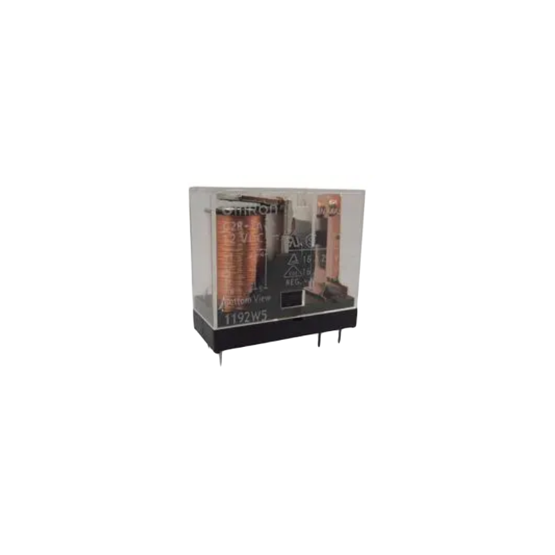
⚡ 58-12 2CO Relay – Dual Changeover Power Relay Module
The 58-12 2CO Relay is a versatile dual-contact power relay featuring two independent changeover (SPDT) contacts in a compact package. With a 12V DC coil and 2CO (2 Changeover) configuration, this relay provides flexible switching capabilities for complex automation, motor direction control, dual-circuit switching, and advanced control applications. Each contact is rated for 10A at 250VAC, making this relay ideal for applications requiring simultaneous control of multiple loads or reversing operations.
✨ Key Highlights
- ⚡ 12V DC Coil – Standard voltage for automotive and battery systems
- 🔄 2CO (2 Changeover) Configuration – DPDT with 2x independent SPDT contacts
- 🔌 Dual 10A Switching – Each contact rated 10A @ 250VAC/30VDC
- 🤖 Motor Reversing Ready – Perfect for bidirectional motor control
- 📐 Compact Design – Space-efficient dual-contact relay
- 💡 Low Coil Power – Efficient operation at ~400-500mW
- 🔧 8-Pin Configuration – All contacts and coil accessible
- ⚙️ Extended Service Life – 100,000+ mechanical operations
- 🛡️ High Isolation – 1000VAC dielectric strength
- 🌐 Versatile Applications – Multi-circuit, reversing, crossover switching
📊 Technical Specifications
| Specification |
Details |
| 📋 Model Number |
58-12 2CO (OEN Series) |
| ⚡ Coil Voltage |
12V DC (Nominal) |
| 🔋 Coil Voltage Range |
9.6V – 14.4V DC (±20%) |
| 💡 Coil Current |
~33-40mA (typical at 12V) |
| ⚙️ Coil Resistance |
~300-360Ω (±10%) |
| ⚡ Coil Power |
~400-480mW |
| 🔌 Contact Configuration |
2CO (2 Changeover) = DPDT (Double Pole Double Throw) |
| 🔢 Number of Contacts |
2 independent changeover contacts (2x NO + 2x NC + 2x COM) |
| ⚡ Contact Rating (AC) |
10A @ 250VAC per contact (Resistive Load) |
| 🔋 Contact Rating (DC) |
10A @ 30VDC per contact (Resistive Load) |
| 💪 Maximum Switching Voltage |
250VAC / 30VDC |
| 🔌 Maximum Switching Current |
10A (Resistive), 5A (Inductive) per contact |
| ⚙️ Contact Material |
Silver Alloy (AgNi or AgSnO2) |
| 🔒 Contact Resistance |
≤100mΩ (initial, max per contact) |
| ⏱️ Operating Time |
≤10ms (pickup), ≤5ms (release) |
| 🔄 Mechanical Life |
10,000,000 operations (no load) |
| ⚡ Electrical Life |
100,000 operations (rated load) |
| 🛡️ Insulation Resistance |
≥100MΩ (at 500VDC) |
| ⚡ Dielectric Strength |
1000VAC (1 minute between coil and contacts) |
| 📐 Mounting Type |
PCB through-hole or relay socket (8-pin) |
| 📌 Pin Pitch |
5.0mm (standard spacing) |
| 🌡️ Operating Temperature |
-40°C to +85°C |
| 💧 Humidity |
5% to 85% RH (non-condensing) |
| 📏 Dimensions (L x W x H) |
~29mm x 12.7mm x 15.7mm |
| ⚖️ Weight |
~12g |
| 🏭 Standards Compliance |
UL, TÜV, CE approved |
🔌 8-Pin Configuration & Pinout
| Pin Number |
Pin Name |
Function |
| 1 |
Coil A1 (+) |
Positive coil terminal (Connect to +12V via driver) |
| 2 |
Contact 1 NC |
Contact 1 Normally Closed (Open when energized) |
| 3 |
Contact 1 COM |
Contact 1 Common (Moving contact) |
| 4 |
Contact 1 NO |
Contact 1 Normally Open (Closed when energized) |
| 5 |
Contact 2 NO |
Contact 2 Normally Open (Closed when energized) |
| 6 |
Contact 2 COM |
Contact 2 Common (Moving contact) |
| 7 |
Contact 2 NC |
Contact 2 Normally Closed (Open when energized) |
| 8 |
Coil A2 (-) |
Negative coil terminal (Connect to GND) |
🔄 DPDT Contact States
🎯 Perfect For
| Application |
Description |
| 🤖 Motor Direction Control |
Reversing DC motors, H-bridge alternative, bidirectional control |
| 🔄 Polarity Reversal |
Switch power supply polarity, battery reversal circuits |
| 🔌 Dual Circuit Switching |
Control two independent loads simultaneously |
| 🚪 Door/Gate Automation |
Open/close control, limit switch integration |
| 🎚️ Crossover Switching |
Audio signal routing, A/B switching, selector circuits |
| 🚗 Automotive Applications |
Window motors, seat adjustment, mirror control |
| 🏠 Curtain/Blind Motors |
Open/close automated window treatments |
| 🏭 Industrial Automation |
Conveyor direction, valve actuators, pneumatic control |
| 🔋 Battery Management |
Charge/discharge switching, backup power routing |
| 📡 Antenna Switching |
RF signal routing, antenna selection, diversity systems |
| 💡 Dual Lighting Control |
Switch between two light circuits, scene selection |
| ⚡ Power Source Selection |
Switch between mains and backup power, redundant supplies |
🤖 DC Motor Reversing Configuration
| Connection |
Wire To |
Function |
| Motor Wire 1 |
Contact 1 COM |
Motor terminal A |
| Motor Wire 2 |
Contact 2 COM |
Motor terminal B |
| Power (+12V) |
Contact 1 NO + Contact 2 NC (tied together) |
Forward: +12V to Motor A, GND to Motor B |
| Ground (GND) |
Contact 1 NC + Contact 2 NO (tied together) |
Reverse: +12V to Motor B, GND to Motor A |
| Result: Relay OFF = Motor Forward | Relay ON = Motor Reverse |
🔧 Driver Circuit Options
| Control Method |
Components Needed |
Best For |
| NPN Transistor (2N2222) |
1x 2N2222, 1x 1kΩ resistor, 1x 1N4007 diode |
⭐⭐⭐ Simple, low-cost, standard method |
| Darlington (TIP120) |
1x TIP120, 1x 1kΩ resistor, 1x 1N4007 diode |
⭐⭐⭐⭐ Higher gain, 3.3V compatible |
| MOSFET (IRLZ44N) |
1x MOSFET, 1x 10kΩ resistor, 1x 1N4007 diode |
⭐⭐⭐⭐⭐ Low heat, high efficiency |
| ULN2003 IC |
1x ULN2003 (controls up to 7 relays) |
⭐⭐⭐⭐⭐ Multiple relays, built-in flyback |
| Relay Module Board |
Pre-built relay module with driver |
⭐⭐⭐⭐⭐ Easiest, beginner-friendly |
| Direct GPIO (NOT RECOMMENDED) |
None |
❌ Can damage MCU (33-40mA exceeds limits) |
⚡ Basic Transistor Driver Circuit
| Connection |
Details |
| MCU GPIO (5V/3.3V) |
→ 1kΩ Resistor → NPN Base (2N2222 or TIP120) |
| NPN Emitter |
→ GND (Common ground) |
| NPN Collector |
→ Relay Coil Pin 8 (A2, Coil -) |
| Relay Coil Pin 1 (A1, Coil +) |
→ +12V Power Supply |
| Flyback Diode (1N4007) |
Cathode (stripe) → +12V, Anode → Coil Pin 8 (parallel to coil) |
| ⚠️ Critical Note |
Common ground between MCU and 12V supply REQUIRED |
🔄 2CO (DPDT) Switching Configurations
| Configuration |
Wiring |
Application |
| Motor Reversing |
Cross-wired polarity swap |
DC motor forward/reverse control |
| Dual Independent Loads |
Each contact controls separate load |
Two lights, fans, or devices ON/OFF together |
| A/B Switching |
Common inputs to two outputs |
Audio source selection, antenna switching |
| Latching Circuit |
Cross-coupled with second relay |
Bistable state retention, flip-flop logic |
| Redundant Power |
Main power on NC, backup on NO |
Automatic failover to backup supply |
| Crossover Network |
Swap two signal paths |
Phase reversal, speaker crossover |
🔄 Load Type Derating Guide
| Load Type |
Max Current @ 12V |
Max Current @ 250VAC |
Notes |
| Resistive (Heaters, Bulbs) |
10A per contact |
10A per contact |
✅ Full rated current |
| LED Loads (with driver) |
10A per contact |
10A per contact |
✅ Low inrush, full rating OK |
| DC Motors (Reversing) |
5A total |
N/A |
⚠️ Derate to 50%, both contacts share load |
| Inductive (Solenoids) |
5A per contact |
5A per contact |
⚠️ Derate 50%, add flyback protection |
| Incandescent Lamps |
6A per contact |
6A per contact |
⚠️ High inrush (10x), derate 40% |
| Capacitive (Power Supplies) |
5A per contact |
5A per contact |
⚠️ High inrush current at turn-on |
⚠️ Critical Safety & Usage Notes
- ⚡ 12V DC coil required – Will not operate reliably below 9.6V
- 🔌 NEVER drive directly from GPIO – 33-40mA exceeds most MCU pin limits
- ⚠️ ALWAYS use flyback diode – Mandatory for protecting driver circuit
- 🔒 Observe coil polarity – Pin 1 = (+), Pin 8 = (-) for best practice
- 💪 10A maximum per contact – Don’t parallel contacts for higher current
- 🤖 Motor reversing caution – Never energize relay while motor running (use brake first)
- 🔥 Inductive loads require derating – Motors 50% reduction (5A max)
- ⚡ AC VOLTAGE IS DANGEROUS – 250VAC can be lethal; use qualified electrician
- 🛡️ Common ground essential – MCU GND and 12V supply GND must connect
- 🔧 Use relay socket recommended – 8-pin socket for easy replacement
- 🌡️ Heat dissipation – Dual contacts generate more heat under full load
- 📏 Contact isolation – Both contacts switch independently but simultaneously
📦 Package Contents
- ✅ 1x 58-12 2CO Relay (8-Pin, 12V DC coil, DPDT)
- ✅ Standard PCB through-hole package
- ✅ Anti-static packaging
- ⚠️ Note: Driver circuit components NOT included
- ⚠️ Note: Flyback diode (1N4007) sold separately
- ⚠️ Note: 8-pin relay socket sold separately (optional)
- ⚠️ Note: 12V power supply NOT included
🔧 Example Arduino Code (Motor Reversing)
| Code Snippet |
// Define relay control pin (connected to transistor base)

const int RELAY_PIN = 7;
void setup() {

  pinMode(RELAY_PIN, OUTPUT);

  digitalWrite(RELAY_PIN, LOW); // Motor forward (relay OFF)

  Serial.begin(9600);

  Serial.println("Motor Control Ready");

}
void loop() {

  // Motor Forward

  Serial.println("Motor: Forward");

  digitalWrite(RELAY_PIN, LOW); // Relay OFF

  delay(3000); // Run forward 3 seconds


  // Stop motor before reversing

  Serial.println("Motor: Stop");

  delay(500); // Brief pause


  // Motor Reverse

  Serial.println("Motor: Reverse");

  digitalWrite(RELAY_PIN, HIGH); // Relay ON

  delay(3000); // Run reverse 3 seconds


  // Stop before changing direction again

  Serial.println("Motor: Stop");

  delay(500);

}
// Wiring for motor reversing:

// Motor+ → COM1, Motor- → COM2

// +12V → NO1 + NC2 (tied), GND → NC1 + NO2 (tied)
|
✅ Advantages of 2CO (DPDT) Relay
| Feature |
Benefit |
| 🔄 Dual Contacts |
Control two circuits with one relay – space and cost efficient |
| 🤖 Motor Reversing |
Perfect polarity reversal without H-bridge complexity |
| 🔌 Independent Switching |
Each contact rated 10A – versatile configuration options |
| 📐 Compact Design |
Smaller than two separate SPDT relays |
| ⚡ Synchronized Switching |
Both contacts operate simultaneously – no timing issues |
| 💡 Low Coil Current |
33-40mA easy to drive with single transistor |
| 🏭 Industrial Quality |
UL/TÜV certified for professional applications |
| 🌡️ Wide Temp Range |
-40°C to +85°C suitable for automotive and industrial |
| 💰 Cost Effective |
More economical than dual relay solution |
| 🔧 Socket Compatible |
8-pin socket available for easy replacement |
🔍 Troubleshooting Guide
| Problem |
Possible Cause |
Solution |
| Relay Doesn’t Click |
Insufficient coil voltage or current |
✅ Check 12V supply, verify transistor operation, test coil (~300-360Ω) |
| Motor Won’t Reverse |
Incorrect wiring configuration |
✅ Verify crossover wiring: +12V to NO1+NC2, GND to NC1+NO2 |
| Motor Runs Both Directions |
Contacts welded or shorted |
✅ Test contacts with multimeter, replace relay if welded |
| Only One Contact Works |
Contact oxidation or damage |
✅ Test each contact separately, clean or replace relay |
| MCU Resets When Switching |
Missing flyback diode causing voltage spike |
✅ Add 1N4007 diode across coil (cathode to +12V) |
| Relay Gets Very Hot |
Overcurrent through contacts |
✅ Measure load current on each contact, reduce if >10A |
| Intermittent Operation |
Poor pin contact or cold solder joint |
✅ Reflow solder joints, clean pins, use relay socket |
| Contacts Arc Excessively |
Switching inductive load without suppression |
✅ Add RC snubber or flyback diode across load |
🛡️ Load Protection Circuits
| Load Type |
Protection Method |
Components |
| DC Motor (Reversing) |
Flyback Diodes |
4x 1N4007 (one across motor, one across each power rail) |
| DC Solenoids |
Flyback Diode |
1N4007 across each solenoid (cathode to +, anode to -) |
| AC Inductive Loads |
RC Snubber |
100Ω + 0.1µF/630V in series, across each contact |
| High Voltage Spikes |
MOV (Varistor) |
Metal Oxide Varistor rated 20% above supply voltage |
| Coil Protection |
Flyback Diode (mandatory) |
1N4007 across relay coil (cathode to Pin 1, anode to Pin 8) |
💡 Pro Tips for DPDT Applications
- 🤖 Motor brake before reversing – Pause 200-500ms between direction changes
- 🔧 Use 8-pin socket – Makes replacement easy, especially for motor applications
- 📏 Proper wire gauge – Use 18 AWG minimum for 8-10A, 16 AWG for safety
- ⚡ Test polarity – Verify motor direction before final installation
- 🛡️ Add motor protection – Use diodes across motor for EMF suppression
- 🔒 Limit switches recommended – Prevent motor over-travel in automation
- 💾 Stock spare relays – Motor reversing causes faster contact wear
- 📋 Label all 8 pins – Complex wiring needs clear documentation
- 🌡️ Monitor temperature – Both contacts under load generate heat
- 🔄 Current balancing – If using both contacts, balance load distribution
- ⚡ Add status LEDs – Visual indication of direction/state helpful
- 🔧 Fuse each circuit – Protect both contact circuits independently
🆚 1CO vs 2CO Comparison
| Feature |
1CO (SPDT) |
2CO (DPDT) |
| Number of Contacts |
1 changeover |
2 independent changeovers |
| Pin Count |
5 pins |
8 pins |
| Motor Reversing |
❌ Not possible |
✅ Perfect for reversing |
| Dual Circuit Control |
❌ Single circuit only |
✅ Two circuits simultaneously |
| Size |
Smaller |
Slightly larger |
| Cost |
💰 Lower |
💰💰 Moderate |
| Best For |
Simple ON/OFF switching |
Reversing, dual control, crossover |
🛡️ Warranty & Support
✅ Genuine OEN series 2CO relay with dual contacts
✅ Factory tested for coil and dual contact operation
✅ Silver alloy contacts for reliable switching
✅ UL, TÜV, CE certified for safety compliance
✅ Rated for 100,000+ electrical operations
✅ Industrial temperature range (-40°C to +85°C)
✅ Standard 8-pin footprint for universal compatibility
✅ Technical datasheet with wiring diagrams included
✅ Fast replacement for defective units
⚠️ Important: Always use appropriate driver circuit and flyback protection. Motor reversing applications require proper pause between direction changes. High voltage wiring requires qualified electrician.